本文记录了使用STONE串口屏控制WS2812B_RGB灯的流程。
RGB灯是一种我们在日常生活中常见的灯具。它应用广泛,例如城市夜景、灯光秀、室内照明、辅助照明、广告模块照明、发光字、柜台照明、购物中心照明、珠宝展示柜照明等。
本项目旨在通过STONE串口屏实现RGB灯的控制:
- 控制灯光颜色
- 控制灯光亮度
- 控制灯的四种模式
STONE控制串口屏
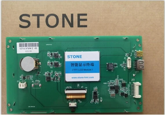
STVC070WT-01
7英寸 STONE STVC070WT-01
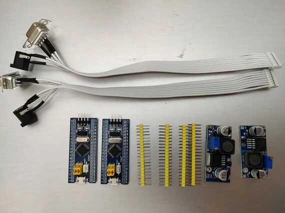
以下图片展示了收到的包装及配件:
清单:
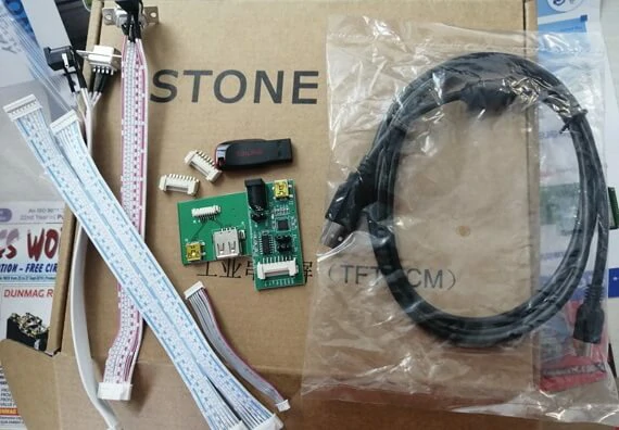
- 连接与接口
- USB转TTL适配板
- USB闪存盘(含开发资料)
- Micro USB 数据线
- USB 数据传输板
- STONE STVC070WT-01 串口屏
- 12V 电源适配器
STONE 控制串口屏的功能
STVC070WT-01 是一款 TFT 显示屏与触摸控制器。它集成了处理器、控制程序、驱动程序、闪存、RS232/RS485/TTL 接口、触摸屏、电源等模块,是一款功能强大的显示系统。
操作系统简单,可由任何单片微控制器控制。
STVC070WT-01 可执行所有基本功能,如文本显示、图像显示、曲线显示、触摸功能、视频和音频功能等。
- 内置 Cortex CPU 和驱动程序
- 可由任何单片微控制器控制
- 显示图片/文本/曲线
- 65536色TFT显示屏
- 支持触摸操作
- RS232/RS485/TTL UART接口及USB端口
- 宽电压范围
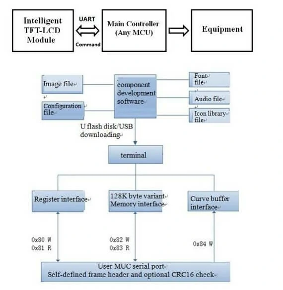
STON石英 串口屏控制显示屏的工作原理
串口屏模块通过命令(十六进制代码)与客户的MCU进行通信,MCU随后根据接收到的命令控制连接的设备工作。
STONE控制串口屏的开发步骤
使用STONE的串口屏模块仅需3步:
- 设计一套美观的图形用户界面。
- 通过 RS232、RS485 或 TTL 直接连接至客户的 MCU。
- 编写简单程序,通过MCU命令控制串口屏模块。(十六进制)
0x12340x120x34
STON 串口屏控制LCD的应用场景
医疗美容设备建筑机械车辆设备电子仪器工业控制系统、电力行业、民用电子设备、自动化设备、交通运输等。
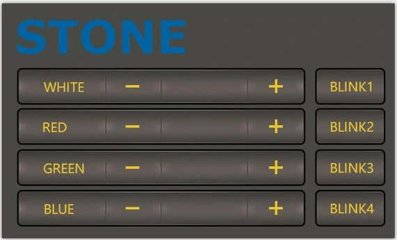
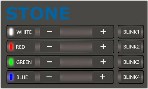
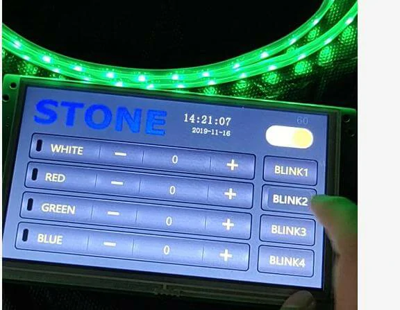
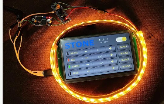
第一张图片为主屏幕图片,第二张图片为按下按钮时的效果。
STONE TOOL box生成LCD模块配置文件
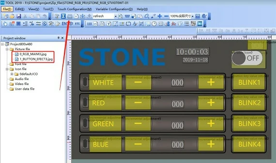
点击箭头所指示的按钮生成配置文件,然后将配置文件下载到串口屏中以显示我们设计的UI界面。
布线与焊接
完成上述触摸屏控制后,我们可以专注于MCU和WS2812B_RGB灯的开发。,我们可以专注于MCU和WS2812B_RGB灯的开发。
但在那之前,
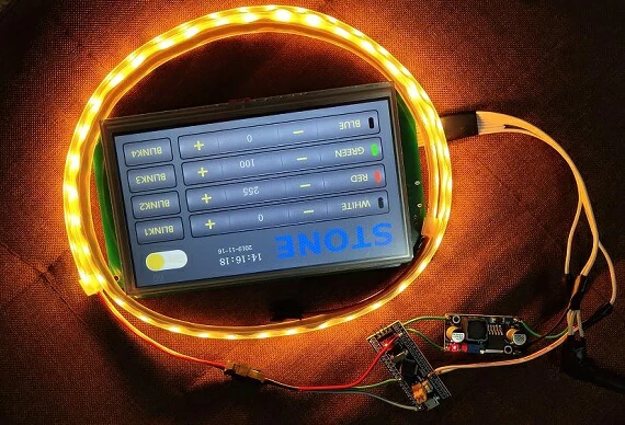
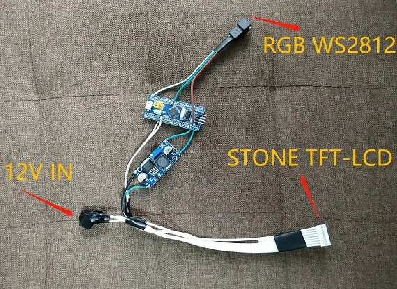
接线图
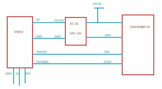
电源适配器为12V,需为STONE STVC070WT-01串口屏供电,并通过DC-DC降压模块将电压降至5V后为MCU模块和WS2812B_RGB灯供电。 STVC070WT-01 串口屏供电,并通过DC-DC降压模块将电压降至5V后为MCU模块和WS2812B_RGB灯供电。
项目中使用的配件
主要配件包括
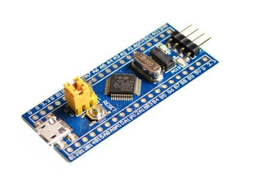
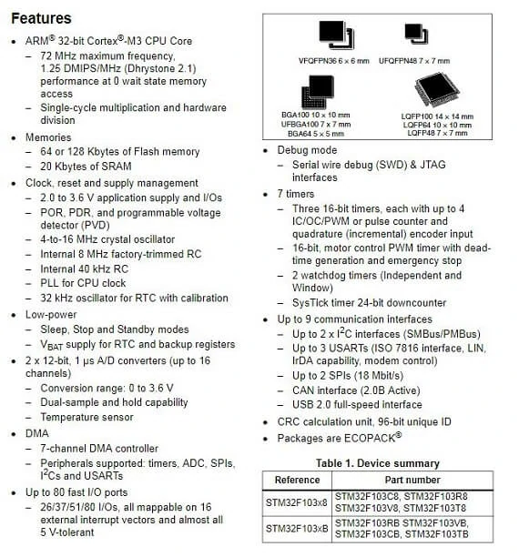
- STM32F103C8R6模块
- DC-DC降压模块
- UART接口
由于STONE STVC070WT-01的默认通信模式为UART-TTL,因此无需使用RS232接口进行连接。移除RS232接口:
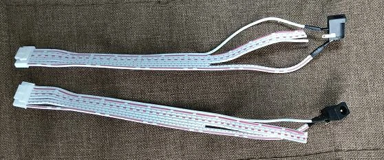
焊接
将这些部件焊接在一起,效果如下:
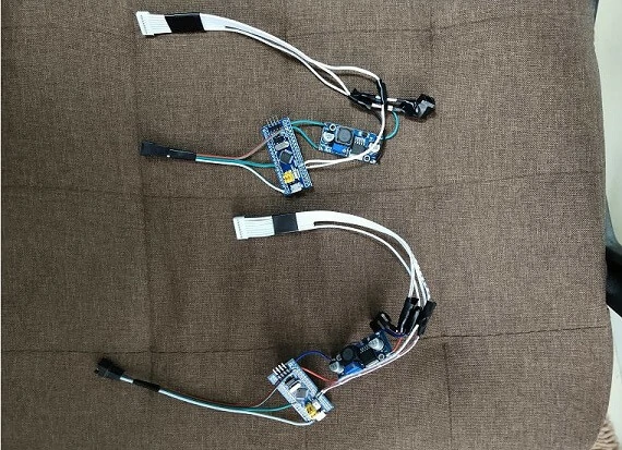
共有3个接口,如上图所示。
当该部分准备就绪后,即可对MCU进行编程。
但在进行编程前,需先确定 WS2812B_RGB 灯的驱动方式。。但在进行编程前,需先确定 WS2812B_RGB 灯的驱动方式。
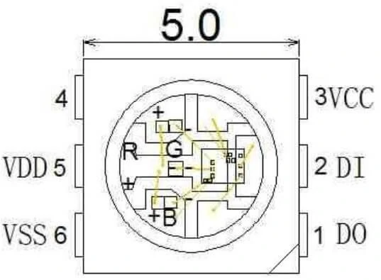
- DOUT:据输出,控制数据信号输出
- DIN:
- VCC:
- NC
- VDD:
- VSS:
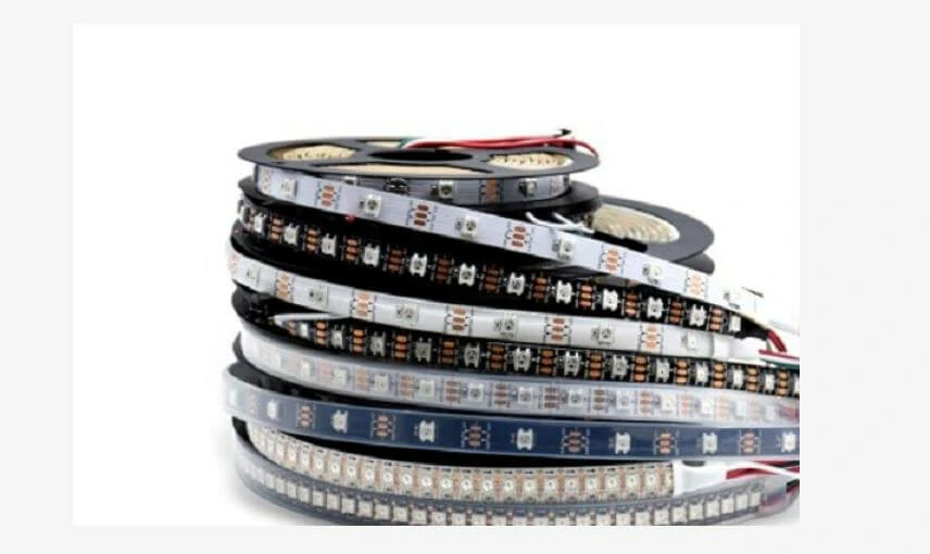
应用领域
LED全彩灯串,LED全彩模块,LED全彩软光条硬光条,LED护栏管,LED点光源,LED像素屏,LED特殊形状屏,各种电子产品,电气设备跑马灯。ED护栏管,LED点光源,LED像素屏,LED特殊形状屏,各种电子产品,电气设备跑马灯。
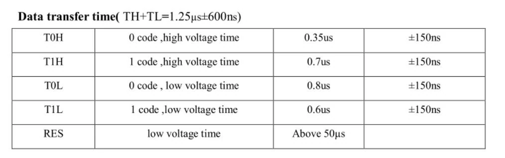
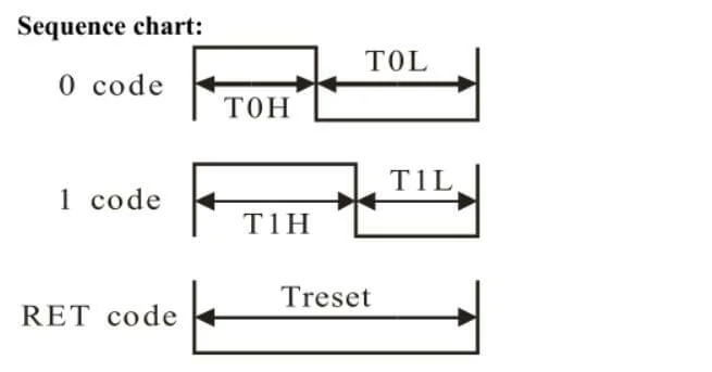
WS2812驱动程序
WS2812的驱动模式简单。MCU只需一条信号线即可完成亮度和颜色控制。
STM32驱动程序代码
#include "../BOARD/ws2812/ws2812.h"#include "usart.h"#include "delay.h"uint8_t PIXEL_NUM=60;#define RGB_LED GPIO_Pin_7#define RGB_LED_HIGH (GPIO_SetBits(GPIOA,RGB_LED))#define RGB_LED_LOW (GPIO_ResetBits(GPIOA,RGB_LED))void RGB_LED_Init(void){GPIO_InitTypeDef GPIO_InitStructure;RCC_APB2PeriphClockCmd(RCC_APB2Periph_GPIOA, ENABLE);GPIO_InitStructure.GPIO_Pin = GPIO_Pin_7;GPIO_InitStructure.GPIO_Mode = GPIO_Mode_Out_PP;GPIO_InitStructure.GPIO_Speed = GPIO_Speed_50MHz;GPIO_Init(GPIOA, &GPIO_InitStructure);GPIO_SetBits(GPIOA,GPIO_Pin_7);}/********************************************************////********************************************************/void RGB_LED_Write0(void){RGB_LED_HIGH;__nop();__nop();__nop();__nop();__nop();__nop();RGB_LED_LOW;__nop();__nop();__nop();__nop();__nop();__nop();__nop();__nop();__nop();__nop();__nop();__nop();__nop();__nop();__nop();__nop();__nop();__nop();__nop();__nop();__nop();__nop();__nop();__nop();__nop();__nop();__nop();__nop();__nop();__nop();__nop();__nop();}/********************************************************////********************************************************/void RGB_LED_Write1(void){RGB_LED_HIGH;__nop();__nop();__nop();__nop();__nop();__nop();__nop();__nop();__nop();__nop();__nop();__nop();__nop();__nop();__nop();__nop();__nop();__nop();__nop();__nop();__nop();__nop();RGB_LED_LOW;__nop();__nop();__nop();__nop();__nop();__nop();__nop();__nop();__nop();__nop();__nop();__nop();}void RGB_LED_Reset(void){RGB_LED_LOW;delay_us(80);}void RGB_LED_Write_Byte(uint8_t byte){uint8_t i;for(i=0;i<8;i++){if(byte&0x80){RGB_LED_Write1();}else{RGB_LED_Write0();}byte <<= 1;}}void RGB_LED_Write_24Bits(uint8_t red,uint8_t green,uint8_t blue){uint16_t i=0;for( i=0;i<pixel_num;i++)< span=""></pixel_num;i++)<>{RGB_LED_Write_Byte(green);RGB_LED_Write_Byte(red);RGB_LED_Write_Byte(blue);}}void RGB_LED_Write_24Bits_Efect(uint8_t red,uint8_t green,uint8_t blue){RGB_LED_Write_Byte(green);RGB_LED_Write_Byte(red);RGB_LED_Write_Byte(blue);}void RGB_LED_Red(void){uint8_t i;//4?LED???for(i=0;i<pixel_num;i++)< span=""></pixel_num;i++)<>{RGB_LED_Write_24Bits(0, 0xff, 0);}}void RGB_LED_Green(void){uint8_t i;for(i=0;i<pixel_num;i++)< span=""></pixel_num;i++)<>{RGB_LED_Write_24Bits(0xff, 0, 0);}}void RGB_LED_Blue(void){uint8_t i;for(i=0;i<pixel_num;i++)< span=""></pixel_num;i++)<>{RGB_LED_Write_24Bits(0x40, 0x50, 0);}}#ifndef __WS2812_H#define __WS2812_H#include "stm32f10x.h"//#define PIXEL_NUM 120extern uint8_t PIXEL_NUM;#define WS_HIGH 0XF8#define WS_LOW 0XE0#define RED_COLOR 0x07#define GREEN_COLOR 0x08#define BLUE_COLOR 0x09#define WHITE_COLOR 0x06#define LED_ALL_ONOFF 0x01#define BLINK1 0x0A#define BLINK2 0x0B#define BLINK3 0x0C#define BLINK4 0x0D#define LightOn 0x00#define LightOff 0x01void RGB_LED_Reset(void);void RGB_LED_Init(void);void RGB_LED_Reset(void);void RGB_LED_Write_24Bits(uint8_t red,uint8_t green,uint8_t blue);void RGB_LED_Write_24Bits_effect(uint8_t red,uint8_t green,uint8_t blue);uint32_t ws281x_wheel(uint8_t wheelPos);void RGB_LED_Write_24Bits_Efect(uint8_t green,uint8_t red,uint8_t blue);#endif /* __WS2812_H */STM32F103C8T6
关于此芯片的材料和开发文档在互联网上有很多。以下是对该芯片的简要介绍。多。以下是对该芯片的简要介绍。
这是 STM32F103C8T6 的开发板,购买链接:
https://www.st.com/en/microcontrollers-microprocessors/stm32f103c8.html
I’m not going to say much about this chip. The chip download code is j-link, as shown below:
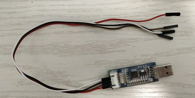
关于这颗芯片,我不再赘述。芯片的下载代码是 j-link,如下所示:
这是j-link的简易版本,仅支持SWD模式调试和下载,不支持JTAG。但对于STM32芯片的开发,SWD调试方式已足够。
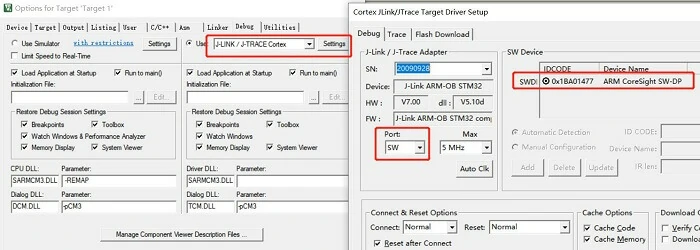
将代码下载到STM32芯片。32芯片。
确保j-link与STM32F103C8T6的连接正确,然后可在KEIL开发环境中识别到芯片:
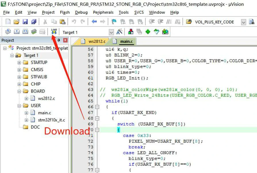
点击下载按钮将代码下载到芯片:
STM32代码
显示屏上的按钮和文本对应特定地址。本项目中显示屏组件的地址定义如下:
#define RED_COLOR 0x07
#define ICON_WHITE_ADDR 0x02
#define ICON_RED_ADDR 0x03
#define ICON_GREEN_ADDR 0x04
#define ICON_BLUE_ADDR 0x05
#define TEXT_RED_ADDR 0x07
#define TEXT_GREEN_ADDR 0x08
#define TEXT_BLUE_ADDR 0x09
#define TEXT_WHITE_ADDR 0x06
#define SWITCH_ONOFF_ADDR 0x01
#define ICON_ON 0x01
#define ICON_OFF 0x00
u8 data_send[8]= {0xA5, 0x5A, 0x05, 0x82, 0x00, 0x00, 0x00,0x00};
Data sent to the display screen should be sent according to the corresponding format:
U8 data_send[8]= {0xA5, 0x5A, 0x05, 0x82, 0x00,0x00,0x00,0x00};
Data [4]\ data[5] is the high and low order of component addresses.
Data [6]\ data[7] is the data to be displayed by the component.
The main logical code will be provided below:
#include "stm32f10x.h"
#include "usart.h"
#include "delay.h"
#include "../BOARD/ws2812/ws2812.h"
struct RGB_COLOR
{
u8 C_RED;
u8 C_GREEN;
u8 C_BLUE;
u8 C_WHITE;
u8 C_RED_FLAG;
u8 C_GREEN_FLAG;
u8 C_BLUE_FLAG;
};
#define ICON_WHITE_ADDR 0x02
#define ICON_RED_ADDR 0x03
#define ICON_GREEN_ADDR 0x04
#define ICON_BLUE_ADDR 0x05
#define TEXT_RED_ADDR 0x07
#define TEXT_GREEN_ADDR 0x08
#define TEXT_BLUE_ADDR 0x09
#define TEXT_WHITE_ADDR 0x06
#define SWITCH_ONOFF_ADDR 0x01
#define ICON_ON 0x01
#define ICON_OFF 0x00
u8 data_send[8]= {0xA5, 0x5A, 0x05, 0x82, 0x00, 0x00, 0x00,0x00};
void UART1_Send_Array(u8 send_array[],unsigned char num)
{
u8 i=0;
while(i<num)< span=""></num)<>
{
USART_SendData(USART1,send_array[i]);
while( USART_GetFlagStatus(USART1,USART_FLAG_TC)!= SET);
i++;
}
}
int main(void)
{
uart_init(115200);
delay_init();
struct RGB_COLOR USER_RGB_COLOR;
USER_RGB_COLOR.C_BLUE=0;
USER_RGB_COLOR.C_GREEN=0;
USER_RGB_COLOR.C_RED=0;
USER_RGB_COLOR.C_RED_FLAG=1;
USER_RGB_COLOR.C_GREEN_FLAG=1;
USER_RGB_COLOR.C_BLUE_FLAG=1;
u16 k,q;
u8 BLINK_2=0;
u8 USER_R=0,USER_G=0,USER_B=0,COLOR_TYPE=0,COLOR_DIR=0;
u8 blink_type=0;
u16 times=0;
RGB_LED_Init();
while(1)
{
if(USART_RX_END)
{
switch (USART_RX_BUF[5])
{
case 0x33:
PIXEL_NUM=USART_RX_BUF[8];
break;
case LED_ALL_ONOFF:
blink_type=0;
if(USART_RX_BUF[8]==0)
{
data_send[5]=ICON_RED_ADDR;
data_send[7]=ICON_OFF;
UART1_Send_Array(data_send,8);
data_send[5]=TEXT_RED_ADDR;
data_send[7]=0x00;
UART1_Send_Array(data_send,8);
data_send[5]=ICON_GREEN_ADDR;
data_send[7]=ICON_OFF;
UART1_Send_Array(data_send,8);
data_send[5]=TEXT_GREEN_ADDR;
data_send[7]=0x00;
UART1_Send_Array(data_send,8);
data_send[5]=ICON_BLUE_ADDR;
data_send[7]=ICON_OFF;
UART1_Send_Array(data_send,8);
data_send[5]=TEXT_BLUE_ADDR;
data_send[7]=0x00;
UART1_Send_Array(data_send,8);
USER_RGB_COLOR.C_BLUE=0;
USER_RGB_COLOR.C_GREEN=0;
USER_RGB_COLOR.C_RED=0;
data_send[5]=ICON_WHITE_ADDR;
data_send[7]=ICON_OFF;
UART1_Send_Array(data_send,8);
data_send[5]=TEXT_WHITE_ADDR;
data_send[7]=0x00;
UART1_Send_Array(data_send,8);
USER_RGB_COLOR.C_WHITE=0;
}
else
{
USER_RGB_COLOR.C_BLUE=0x32;
USER_RGB_COLOR.C_GREEN=0x10;
USER_RGB_COLOR.C_RED=0x24;
USER_RGB_COLOR.C_RED_FLAG=0;
USER_RGB_COLOR.C_GREEN_FLAG=0;
USER_RGB_COLOR.C_BLUE_FLAG=0;
data_send[5]=ICON_RED_ADDR;
data_send[7]=ICON_ON;
UART1_Send_Array(data_send,8);
data_send[5]=TEXT_RED_ADDR;
data_send[7]=0x24;
UART1_Send_Array(data_send,8);
data_send[5]=ICON_GREEN_ADDR;
data_send[7]=ICON_ON;
UART1_Send_Array(data_send,8);
data_send[5]=TEXT_GREEN_ADDR;
data_send[7]=0x10;
UART1_Send_Array(data_send,8);
data_send[5]=ICON_BLUE_ADDR;
data_send[7]=ICON_ON;
UART1_Send_Array(data_send,8);
data_send[5]=TEXT_BLUE_ADDR;
data_send[7]=0x32;
UART1_Send_Array(data_send,8);
}
RGB_LED_Write_24Bits(USER_RGB_COLOR.C_RED, USER_RGB_COLOR.C_GREEN, USER_RGB_COLOR.C_BLUE);
break;
case RED_COLOR:
blink_type=0;
if(USER_RGB_COLOR.C_RED_FLAG==1)
{
if(USART_RX_BUF[8]==0)
break;
}
data_send[5]=ICON_WHITE_ADDR;
data_send[7]=ICON_OFF;
UART1_Send_Array(data_send,8);
data_send[5]=TEXT_WHITE_ADDR;
data_send[7]=0x00;
UART1_Send_Array(data_send,8);
USER_RGB_COLOR.C_WHITE=0;
data_send[5]=SWITCH_ONOFF_ADDR;
data_send[7]=ICON_ON;
UART1_Send_Array(data_send,8);
data_send[5]=ICON_RED_ADDR;
if(USART_RX_BUF[8]>0)data_send[7]=ICON_ON;
else data_send[7]=ICON_OFF;
UART1_Send_Array(data_send,8);
USER_RGB_COLOR.C_RED=USART_RX_BUF[8];
USER_RGB_COLOR.C_RED_FLAG=0;
if(USER_RGB_COLOR.C_RED==0)USER_RGB_COLOR.C_RED_FLAG=1;
if((USER_RGB_COLOR.C_RED==0x00)&&(USER_RGB_COLOR.C_GREEN==0x00)&&(USER_RGB_COLOR.C_BLUE==0x00)&&(USER_RGB_COLOR.C_WHITE==0x00))
{
data_send[5]=SWITCH_ONOFF_ADDR;
data_send[7]=ICON_OFF;
UART1_Send_Array(data_send,8);
}
RGB_LED_Write_24Bits(USER_RGB_COLOR.C_RED, USER_RGB_COLOR.C_GREEN, USER_RGB_COLOR.C_BLUE); // Red
break;
case GREEN_COLOR:
blink_type=0;
if(USER_RGB_COLOR.C_GREEN_FLAG==1)
{
if(USART_RX_BUF[8]==0)
break;
}
data_send[5]=ICON_GREEN_ADDR;
if(USART_RX_BUF[8]>0)data_send[7]=ICON_ON;
else data_send[7]=ICON_OFF;
UART1_Send_Array(data_send,8);
data_send[5]=ICON_WHITE_ADDR;
data_send[7]=ICON_OFF;
UART1_Send_Array(data_send,8);
data_send[5]=TEXT_WHITE_ADDR;
data_send[7]=0x00;
UART1_Send_Array(data_send,8);
USER_RGB_COLOR.C_WHITE=0;
data_send[5]=SWITCH_ONOFF_ADDR;
data_send[7]=ICON_ON;
UART1_Send_Array(data_send,8);
USER_RGB_COLOR.C_GREEN=USART_RX_BUF[8];
USER_RGB_COLOR.C_GREEN_FLAG=0;
if(USER_RGB_COLOR.C_GREEN==0)USER_RGB_COLOR.C_GREEN_FLAG=1;
if((USER_RGB_COLOR.C_RED==0x00)&&(USER_RGB_COLOR.C_GREEN==0x00)&&(USER_RGB_COLOR.C_BLUE==0x00)&&(USER_RGB_COLOR.C_WHITE==0x00))
{
data_send[5]=SWITCH_ONOFF_ADDR;
data_send[7]=ICON_OFF;
UART1_Send_Array(data_send,8);
}
RGB_LED_Write_24Bits(USER_RGB_COLOR.C_RED, USER_RGB_COLOR.C_GREEN, USER_RGB_COLOR.C_BLUE); // Green
break;
case BLUE_COLOR:
blink_type=0;
if(USER_RGB_COLOR.C_BLUE_FLAG==1)
{
if(USART_RX_BUF[8]==0)
break;
}
data_send[5]=ICON_BLUE_ADDR;
if(USART_RX_BUF[8]>0)data_send[7]=ICON_ON;
else data_send[7]=ICON_OFF;
UART1_Send_Array(data_send,8);
data_send[5]=ICON_WHITE_ADDR;
data_send[7]=ICON_OFF;
UART1_Send_Array(data_send,8);
data_send[5]=TEXT_WHITE_ADDR;
data_send[7]=0x00;
UART1_Send_Array(data_send,8);
USER_RGB_COLOR.C_WHITE=0;
data_send[5]=SWITCH_ONOFF_ADDR;
data_send[7]=ICON_ON;
UART1_Send_Array(data_send,8);
USER_RGB_COLOR.C_BLUE=USART_RX_BUF[8];
USER_RGB_COLOR.C_BLUE_FLAG=0;
if(USER_RGB_COLOR.C_BLUE==0)USER_RGB_COLOR.C_BLUE_FLAG=1;
if((USER_RGB_COLOR.C_RED==0x00)&&(USER_RGB_COLOR.C_GREEN==0x00)&&(USER_RGB_COLOR.C_BLUE==0x00)&&(USER_RGB_COLOR.C_WHITE==0x00))
{
data_send[5]=SWITCH_ONOFF_ADDR;
data_send[7]=ICON_OFF;
UART1_Send_Array(data_send,8);
}
RGB_LED_Write_24Bits(USER_RGB_COLOR.C_RED, USER_RGB_COLOR.C_GREEN, USER_RGB_COLOR.C_BLUE); // Blue
break;
case WHITE_COLOR:
blink_type=0;
data_send[5]=ICON_WHITE_ADDR;
if(USART_RX_BUF[8]>0)data_send[7]=ICON_ON;
else data_send[7]=ICON_OFF;
UART1_Send_Array(data_send,8);
data_send[5]=ICON_RED_ADDR;
data_send[7]=ICON_OFF;
UART1_Send_Array(data_send,8);
data_send[5]=TEXT_RED_ADDR;
data_send[7]=0x00;
UART1_Send_Array(data_send,8);
data_send[5]=ICON_GREEN_ADDR;
data_send[7]=ICON_OFF;
UART1_Send_Array(data_send,8);
data_send[5]=TEXT_GREEN_ADDR;
data_send[7]=0x00;
UART1_Send_Array(data_send,8);
data_send[5]=ICON_BLUE_ADDR;
data_send[7]=ICON_OFF;
UART1_Send_Array(data_send,8);
data_send[5]=TEXT_BLUE_ADDR;
data_send[7]=0x00;
UART1_Send_Array(data_send,8);
USER_RGB_COLOR.C_BLUE=0;
USER_RGB_COLOR.C_GREEN=0;
USER_RGB_COLOR.C_RED=0;
USER_RGB_COLOR.C_RED_FLAG=1;
USER_RGB_COLOR.C_GREEN_FLAG=1;
USER_RGB_COLOR.C_BLUE_FLAG=1;
data_send[5]=SWITCH_ONOFF_ADDR;
data_send[7]=ICON_ON;
UART1_Send_Array(data_send,8);
USER_RGB_COLOR.C_WHITE=USART_RX_BUF[8];
if((USER_RGB_COLOR.C_RED==0x00)&&(USER_RGB_COLOR.C_GREEN==0x00)&&(USER_RGB_COLOR.C_BLUE==0x00)&&(USER_RGB_COLOR.C_WHITE==0x00))
{
data_send[5]=SWITCH_ONOFF_ADDR;
data_send[7]=ICON_OFF;
UART1_Send_Array(data_send,8);
}
RGB_LED_Write_24Bits(USER_RGB_COLOR.C_WHITE, USER_RGB_COLOR.C_WHITE, USER_RGB_COLOR.C_WHITE);
break;
case BLINK1:
blink_type=1;
data_send[5]=ICON_RED_ADDR;
data_send[7]=ICON_OFF;
UART1_Send_Array(data_send,8);
data_send[5]=TEXT_RED_ADDR;
data_send[7]=0x00;
UART1_Send_Array(data_send,8);
data_send[5]=ICON_GREEN_ADDR;
data_send[7]=ICON_OFF;
UART1_Send_Array(data_send,8);
data_send[5]=TEXT_GREEN_ADDR;
data_send[7]=0x00;
UART1_Send_Array(data_send,8);
data_send[5]=ICON_BLUE_ADDR;
data_send[7]=ICON_OFF;
UART1_Send_Array(data_send,8);
data_send[5]=TEXT_BLUE_ADDR;
data_send[7]=0x00;
UART1_Send_Array(data_send,8);
USER_RGB_COLOR.C_BLUE=0;
USER_RGB_COLOR.C_GREEN=0;
USER_RGB_COLOR.C_RED=0;
data_send[5]=ICON_WHITE_ADDR;
data_send[7]=ICON_OFF;
UART1_Send_Array(data_send,8);
data_send[5]=TEXT_WHITE_ADDR;
data_send[7]=0x00;
UART1_Send_Array(data_send,8);
USER_RGB_COLOR.C_WHITE=0;
data_send[5]=SWITCH_ONOFF_ADDR;
data_send[7]=ICON_ON;
UART1_Send_Array(data_send,8);
break;
case BLINK2:
blink_type=2;
data_send[5]=ICON_RED_ADDR;
data_send[7]=ICON_OFF;
UART1_Send_Array(data_send,8);
data_send[5]=TEXT_RED_ADDR;
data_send[7]=0x00;
UART1_Send_Array(data_send,8);
data_send[5]=ICON_GREEN_ADDR;
data_send[7]=ICON_OFF;
UART1_Send_Array(data_send,8);
data_send[5]=TEXT_GREEN_ADDR;
data_send[7]=0x00;
UART1_Send_Array(data_send,8);
data_send[5]=ICON_BLUE_ADDR;
data_send[7]=ICON_OFF;
UART1_Send_Array(data_send,8);
data_send[5]=TEXT_BLUE_ADDR;
data_send[7]=0x00;
UART1_Send_Array(data_send,8);
USER_RGB_COLOR.C_BLUE=0;
USER_RGB_COLOR.C_GREEN=0;
USER_RGB_COLOR.C_RED=0;
data_send[5]=ICON_WHITE_ADDR;
data_send[7]=ICON_OFF;
UART1_Send_Array(data_send,8);
data_send[5]=TEXT_WHITE_ADDR;
data_send[7]=0x00;
UART1_Send_Array(data_send,8);
USER_RGB_COLOR.C_WHITE=0;
data_send[5]=SWITCH_ONOFF_ADDR;
data_send[7]=ICON_ON;
UART1_Send_Array(data_send,8);
break;
case BLINK3:
blink_type=3;
data_send[5]=ICON_RED_ADDR;
data_send[7]=ICON_OFF;
UART1_Send_Array(data_send,8);
data_send[5]=TEXT_RED_ADDR;
data_send[7]=0x00;
UART1_Send_Array(data_send,8);
data_send[5]=ICON_GREEN_ADDR;
data_send[7]=ICON_OFF;
UART1_Send_Array(data_send,8);
data_send[5]=TEXT_GREEN_ADDR;
data_send[7]=0x00;
UART1_Send_Array(data_send,8);
data_send[5]=ICON_BLUE_ADDR;
data_send[7]=ICON_OFF;
UART1_Send_Array(data_send,8);
data_send[5]=TEXT_BLUE_ADDR;
data_send[7]=0x00;
UART1_Send_Array(data_send,8);
USER_RGB_COLOR.C_BLUE=0;
USER_RGB_COLOR.C_GREEN=0;
USER_RGB_COLOR.C_RED=0;
// USER_RGB_COLOR.C_RED_FLAG=1;
// USER_RGB_COLOR.C_GREEN_FLAG=1;
// USER_RGB_COLOR.C_BLUE_FLAG=1;
data_send[5]=ICON_WHITE_ADDR;
data_send[7]=ICON_OFF;
UART1_Send_Array(data_send,8);
data_send[5]=TEXT_WHITE_ADDR;
data_send[7]=0x00;
UART1_Send_Array(data_send,8);
USER_RGB_COLOR.C_WHITE=0;
data_send[5]=SWITCH_ONOFF_ADDR;
data_send[7]=ICON_ON;
UART1_Send_Array(data_send,8);
break;
case BLINK4:
blink_type=4;
data_send[5]=ICON_RED_ADDR;
data_send[7]=ICON_OFF;
UART1_Send_Array(data_send,8);
data_send[5]=TEXT_RED_ADDR;
data_send[7]=0x00;
UART1_Send_Array(data_send,8);
data_send[5]=ICON_GREEN_ADDR;
data_send[7]=ICON_OFF;
UART1_Send_Array(data_send,8);
data_send[5]=TEXT_GREEN_ADDR;
data_send[7]=0x00;
UART1_Send_Array(data_send,8);
data_send[5]=ICON_BLUE_ADDR;
data_send[7]=ICON_OFF;
UART1_Send_Array(data_send,8);
data_send[5]=TEXT_BLUE_ADDR;
data_send[7]=0x00;
UART1_Send_Array(data_send,8);
USER_RGB_COLOR.C_BLUE=0;
USER_RGB_COLOR.C_GREEN=0;
USER_RGB_COLOR.C_RED=0;
data_send[5]=ICON_WHITE_ADDR;
data_send[7]=ICON_OFF;
UART1_Send_Array(data_send,8);
data_send[5]=TEXT_WHITE_ADDR;
data_send[7]=0x00;
UART1_Send_Array(data_send,8);
USER_RGB_COLOR.C_WHITE=0;
data_send[5]=SWITCH_ONOFF_ADDR;
data_send[7]=ICON_ON;
UART1_Send_Array(data_send,8);
break;
default:
USART_RX_END=0;
USART_RX_STA=0;
break;
}
USART_RX_STA=0;
USART_RX_END=0;
}
else
{
if(blink_type==1)
{
times++;
if(times>=14)
{
times=0;
if(COLOR_DIR==0)
{
if(COLOR_TYPE==0)
{
USER_R++;
USER_G=0;
USER_B=0;
}
else if(COLOR_TYPE==1)
{
USER_R=0;
USER_G++;
USER_B=0;
}
else if(COLOR_TYPE==2)
{
USER_R=0;
USER_G=0;
USER_B++;
}
else if(COLOR_TYPE==3)
{
USER_R++;
USER_G++;
USER_B=0;
}
else if(COLOR_TYPE==4)
{
USER_R=0;
USER_G++;
USER_B++;
}
else if(COLOR_TYPE==5)
{
USER_R++;
USER_G=0;
USER_B++;
}
if((USER_R>=250)||(USER_G>=250)||(USER_B>=250))
{
COLOR_DIR=1;
}
}
else
{
if(COLOR_TYPE==0)
{
USER_R--;
USER_G=0;
USER_B=0;
}
else if(COLOR_TYPE==1)
{
USER_R=0;
USER_G--;
USER_B=0;
}
else if(COLOR_TYPE==2)
{
USER_R=0;
USER_G=0;
USER_B--;
}
else if(COLOR_TYPE==3)
{
USER_R--;
USER_G--;
USER_B=0;
}
else if(COLOR_TYPE==4)
{
USER_R=0;
USER_G--;
USER_B--;
}
else if(COLOR_TYPE==5)
{
USER_R--;
USER_G=0;
USER_B--;
}
if((USER_R==0x02)||(USER_G==0x02)||(USER_B==0x02))
{
COLOR_DIR=0;
COLOR_TYPE++;
if(COLOR_TYPE>5)
COLOR_TYPE=0;
}
}
RGB_LED_Write_24Bits(USER_R,USER_G,USER_B);
}
delay_ms(1);
}
else if(blink_type==2)
{
k++;
if(k>=150)
{
k=0;
q=200;
{
BLINK_2++;
if(BLINK_2>8)BLINK_2=0;
}
if(BLINK_2==0)
RGB_LED_Write_24Bits(q,0,0);
else if(BLINK_2==1)
RGB_LED_Write_24Bits(0,q,0);
else if(BLINK_2==2)
RGB_LED_Write_24Bits(0,0,q);
else if(BLINK_2==3)
RGB_LED_Write_24Bits(q,q,0);
else if(BLINK_2==4)
RGB_LED_Write_24Bits(0,q,q);
else if(BLINK_2==5)
RGB_LED_Write_24Bits(q,0,q);
else if(BLINK_2==6)
RGB_LED_Write_24Bits(q-100,q,0);
else if(BLINK_2==7)
RGB_LED_Write_24Bits(0,q-80,q);
else if(BLINK_2==8)
RGB_LED_Write_24Bits(q,0,q-120);
else if(BLINK_2==9)
RGB_LED_Write_24Bits(40,q-100,q-70);
else if(BLINK_2==10)
RGB_LED_Write_24Bits(q,100,q-80);
}
delay_ms(1);
}
else if(blink_type==3)
{
k++;
if(k>=1000)
{
k=0;
{
BLINK_2++;
if(BLINK_2>5)BLINK_2=0;
}
{
if(BLINK_2==0)
RGB_LED_Write_24Bits(q,0,0);
else if(BLINK_2==1)
RGB_LED_Write_24Bits(0,q,0);
else if(BLINK_2==2)
RGB_LED_Write_24Bits(0,0,q);
else if(BLINK_2==3)
RGB_LED_Write_24Bits(q,q,0);
else if(BLINK_2==4)
RGB_LED_Write_24Bits(0,q,q);
else if(BLINK_2==5)
RGB_LED_Write_24Bits(q,0,q);
}
}
delay_ms(1);
}
else if(blink_type==4)
{
k++;
if(k>=500)
{
k=0;
q=0;
BLINK_2++;
if(BLINK_2>5)BLINK_2=0;
}
q++;
if(q>=250)q=0;
if(BLINK_2==0)
RGB_LED_Write_24Bits(q,0,0);
else if(BLINK_2==1)
RGB_LED_Write_24Bits(0,q,0);
else if(BLINK_2==2)
RGB_LED_Write_24Bits(0,0,q);
else if(BLINK_2==3)
RGB_LED_Write_24Bits(q,q,0);
else if(BLINK_2==4)
RGB_LED_Write_24Bits(0,q,q);
else if(BLINK_2==5)
RGB_LED_Write_24Bits(q,0,q);
delay_ms(1);
}
else
{
}
}
}
}
最后,将代码下载到STM32芯片中,将完成的电路板连接到控制显示屏,并确保电源稳定。然后可以通过STONE控制串口屏控制RGB灯的亮度和颜色。NE控制串口屏控制RGB灯的亮度和颜色。
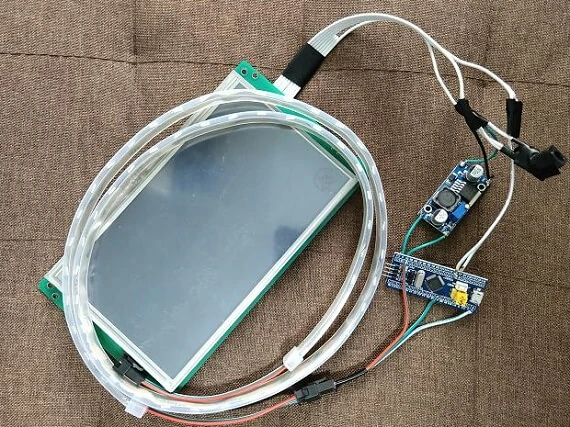
最终硬件连接图