STONE串行串口屏显示器
STONE串行串口屏具有广泛的应用范围,涵盖民用、医疗、精密测量仪器等领域。现在,我将使用一块5英寸的STONE串行HMI屏幕来制作一个简易电子秤。
所需模块如下:
- STONE STVC050WT-01串口屏串口显示模块
- STM32F103RC 开发板
- 压力采集模块
- ADC 转换模块
硬件连接原理图如下:
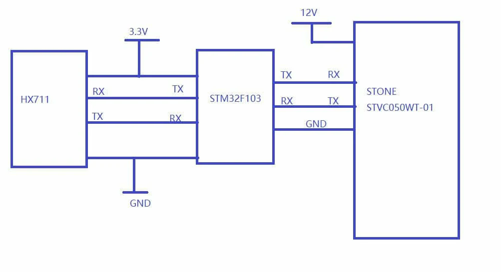
所有硬件模块均按该原理图的连接原则进行连接。
显示内容如下:
- 通过 STONE 显示模块显示托盘上当前放置物品的重量。
- 用户可执行三种操作:去皮、单位转换和归零。
通过在线商城购买的电子秤模块
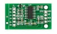
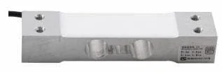
主要分为两部分,其中一部分是HX711准替代模块。
另一部分是压力传感器模块。
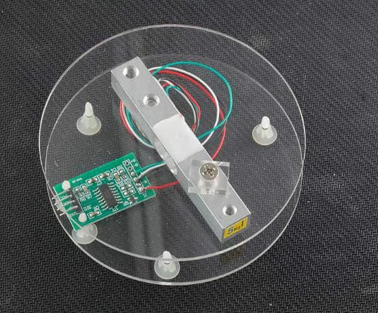
这两部分连接后的效果可参考下图。我添加了另一个托盘:
STONE STVI050WT-01显示模块描述
在本项目中,我使用了STONE STVC050WT-01的串口屏串口显示屏作为用户界面。
该STONE显示屏已集成驱动芯片,用户可直接使用上层计算机,只需通过计算机设计UI图像,添加按钮、文本框等,然后生成配置文件下载至显示屏即可运行。
STVC050WT-01显示屏通过UART-TTL信号与MCU通信,而STM32 MCU的UART恰好处于TTL逻辑电平,因此STONE显示屏与STM32可直接通过UART进行通信。
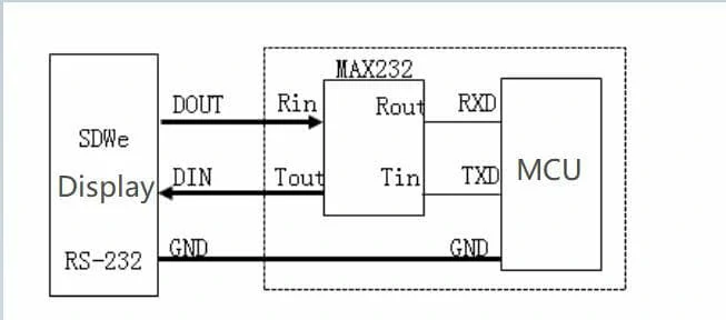
此外,STONE官方网站还销售支持UART-232逻辑电平的串口触摸显示屏。当使用支持 UART-232 的显示屏时,只需添加一个 MAX232 芯片进行逻辑电平转换,即可与 SCM 通信。
如果您不确定如何使用 MAX3232,请参考以下图片:
如果电平转换过于麻烦,可以使用其他类型的显示屏。部分型号可直接输出 UART-TTL 信号。
网站上有详细信息和介绍:https://www.stone-hmi.com//
如果您想使用视频教程和教程,也可以下载官方网站。
开发 STONE 串口屏串口显示模块需要什么?
STONE 显示模块的开发主要分为三个步骤:
- 使用 STONE TOOL 软件设计显示逻辑和按钮逻辑,并将设计文件下载到显示模块。
- MCU 通过串口与 STONE LCD 显示模块通信。
- 根据步骤 2 获取的数据,MCU 执行其他操作。
当然,前提之一是设计一套美观的 UI 界面,通常以 JPEG 格式保存。
在上述三个步骤中,我们需要在电脑上安装以下软件:
- STONE TOOL2019
- Photoshop或其他图形设计软件
使用STONE TOOL软件
从官方网站下载STONE TOOL软件的最新版本(当前为TOOL2019)并安装。
安装完成后,将打开以下界面:
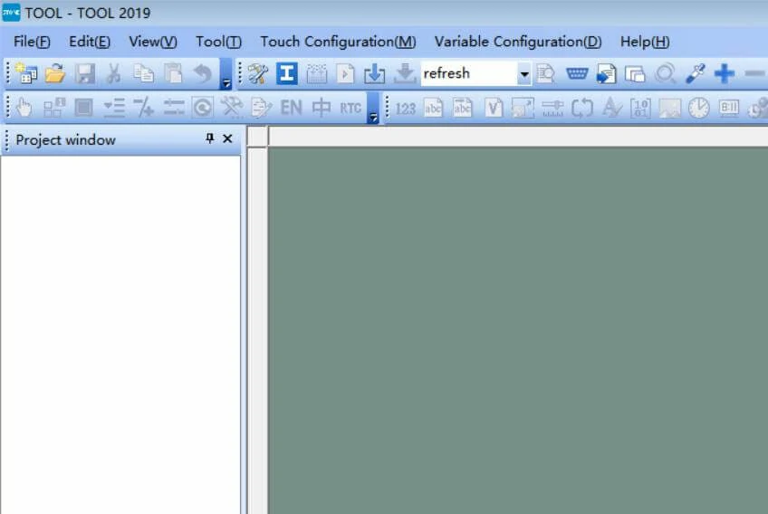
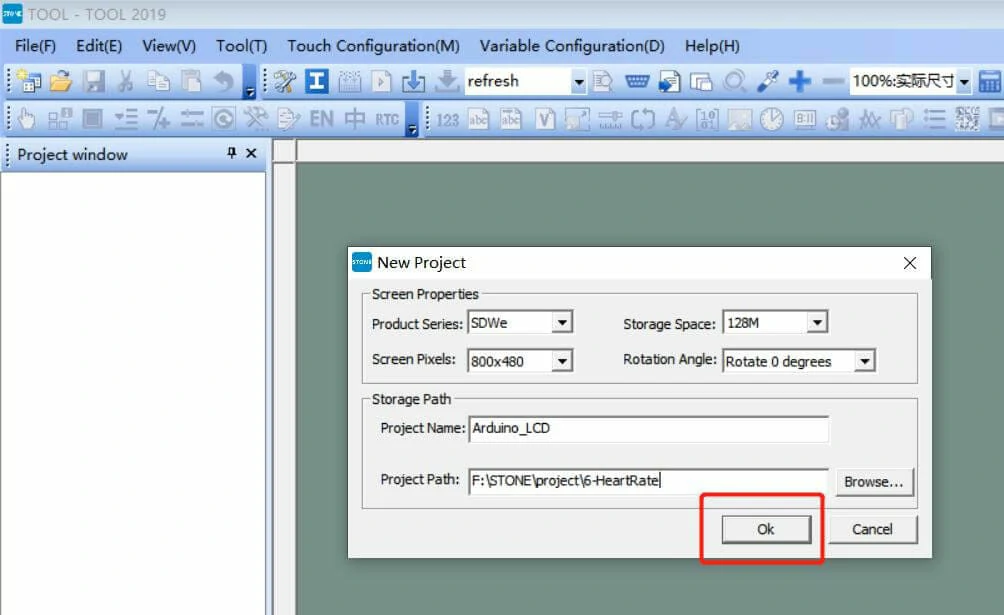
点击左上角的“文件”按钮创建新项目,具体操作将在后续步骤中详细说明。
Photoshop主要用于制作UI界面。在STONE串口屏串口显示设备中,所有用户界面均以图片形式加载并显示,而文字则采用屏幕内置的字体。
如何使用STONE TOOL软件?
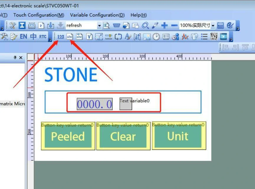
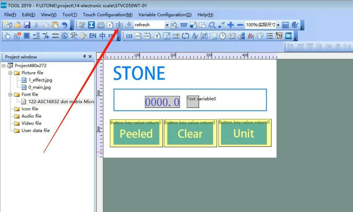
首先,我们需要使用Photoshop设计一套UI界面。以下界面是我使用Photoshop设计的非常简单的UI图片:
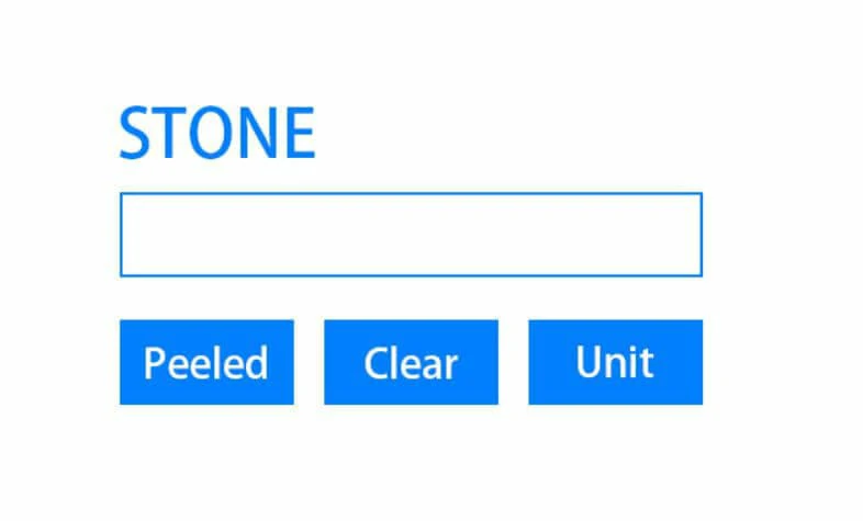
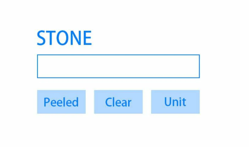
第一张图片是主显示界面。用户将图片下载到STONE串口串口屏显示器后,屏幕在通电后会继续显示该图片。图片中包含一个文本显示框和三个按钮。TOOL 2019软件可配置按钮按下时STONE屏幕通过串口发送的数据内容。
同一TOOL2019软件还允许配置文本显示框的显示方式。
在本项目中,当按下“Peeled”按钮时,STONE屏幕将通过UART向STM32 MCU发送指令,STM32微控制器在接收到指令后,将忽略当前采集的压力传感器值。
“清除”按钮用于清除显示内容,“单位”按钮用于切换显示单位。
在 TOOL 2019 软件中设计 UI 逻辑
设计好用于显示图像的 UI 后,将其保存为 JPG 格式。
打开 STONE TOOL2019 软件并创建新项目:
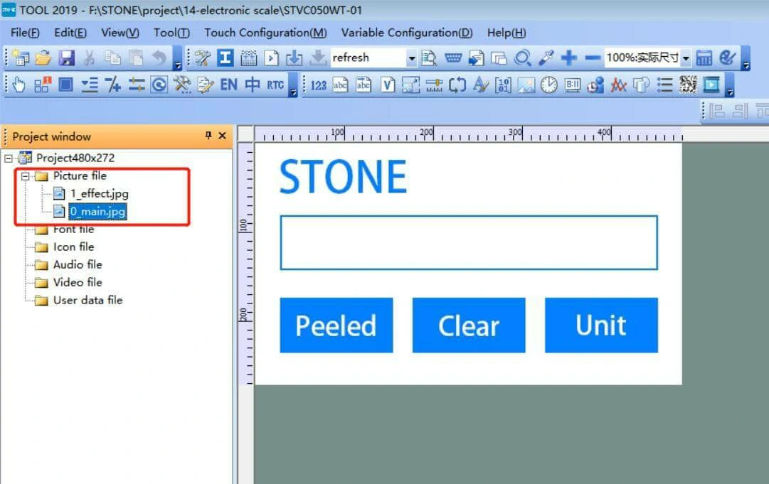
删除新项目默认加载的图像,然后添加我们自己的 UI 图像。
可以看到我们刚刚设计的两个UI图像已加载。
设计按钮逻辑
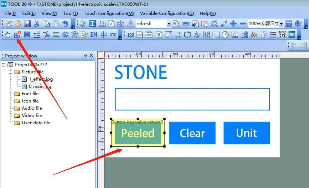
T组件由带箭头的按钮组件表示,将其添加到“剥离”区域,相关组件属性如下:
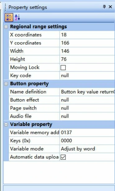
X坐标:组件在整体UI中的X坐标位置
Y坐标:组件在整体UI界面中的Y方向位置
宽度&高度:组件的宽度和高度
移动锁定:固定位置
名称定义:组件的名称
按钮效果:按下按钮时的效果
页面切换:按下按钮切换到下一页,或为空如果不存在
音频文件:按下按钮时播放的音频文件
变量内存地址:组件在显示中的地址
我主要修改了两个地方:
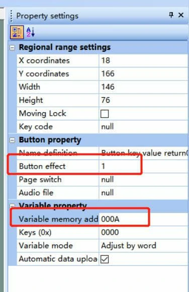
修改后,按下按钮时,按钮的效果为“1_effect”页面的效果,随后STONE屏幕通过串口屏串口向MCU发送“000A”。
其他两个按钮以类似方式添加。
添加数据文本组件
我们只需显示两组数据,即电子秤的重量数据和单位。
这两组数据包含数字和字母,因此需要分开显示。
右侧的“属性设置”是组件的属性设置,包括组件位置、大小、名称、初始值、数据长度、组件地址等。
这里需要说明的是组件地址。每个组件都有独立的组件地址。图中显示的组件地址为0x0133。
这由组件地址决定。
模拟运行
点击生成配置文件并模拟运行以查看效果。
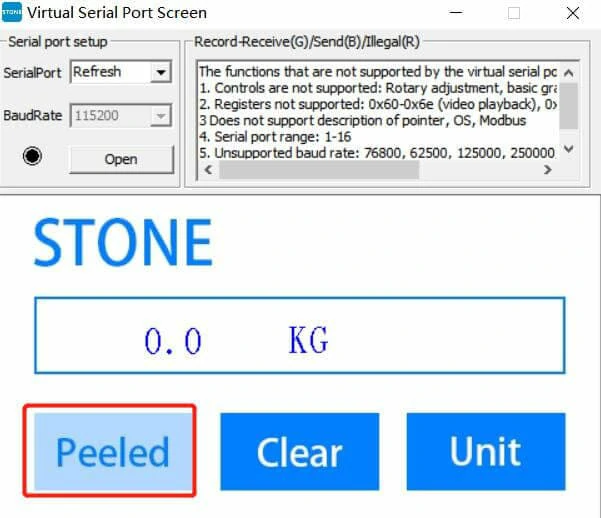
红色区域为按下按钮后的效果。
修改STONE串口串口屏显示器的UART波特率
显示器支持在以下界面修改UART波特率:
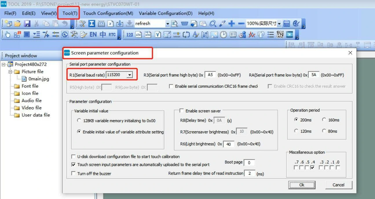
最大波特率为921600,本例中使用115200。
修改波特率实际上是修改STONE串口串口屏显示模块中寄存器R1、R5和R9的值:
当R1为0x00-0x10时,R5和R9无效。
当R1等于0x11时,波特率由R5和R9决定。
生成配置文件并将其下载到STONE屏幕。
完成上述UI界面设计后,可生成配置文件并下载至STVC050WT-01显示模块。此部分操作在STONE开发资料中已有详细说明。
执行步骤 1 后,将 USB 驱动器插入计算机,磁盘将被显示。然后点击“下载到 U 盘”将配置文件下载到 USB 驱动器,并将 USB 驱动器插入 STVC050WT-01 以完成升级。
然后点击“在线下载”并按照提示将配置文件更新到 STONE 显示模块。
将配置文件下载至 STONE 串口触摸显示屏后,即可开始 STM32 MCU 编程。
以下是几个组件的地址:
文本值显示地址:0x000d
单位值显示地址:0x000e
剥离按钮地址:0x000a
“清除”按钮地址:0x000b
“单位”按钮地址:0x000c
HX711模块
简要介绍
HX711是一款专为高精度电子秤设计的24位A/D转换芯片。压力传感器实际上是电阻值的变化,最终通过HX711进行采集转换,再由STM32进行采集。
在本项目中,我们只需了解 HX711 的输出数据是什么,以及如何通过 STM32 采集 HX711 的数据。
HX711 模块有四个接口:
1,VCC
2,GND
这部分的编程原理将在后续的 STM32 编程中体现。
硬件原理
HX711模块的原理图如下:
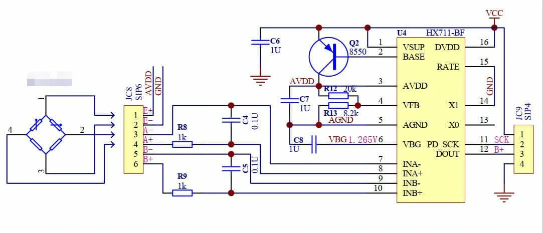
左侧是一个由四个电阻组成的桥式传感器。不同物体的重量会改变对应的电阻值,然后通过HX711转换为实际重量。
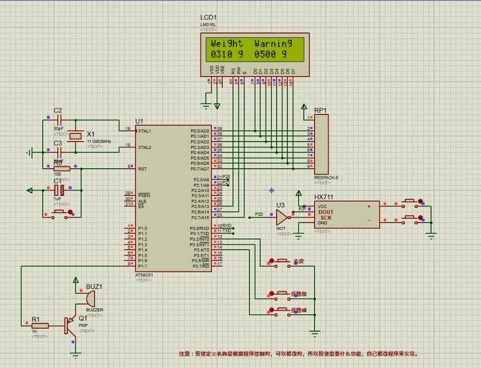
在51 MCU中,可以使用Proteus软件进行仿真:
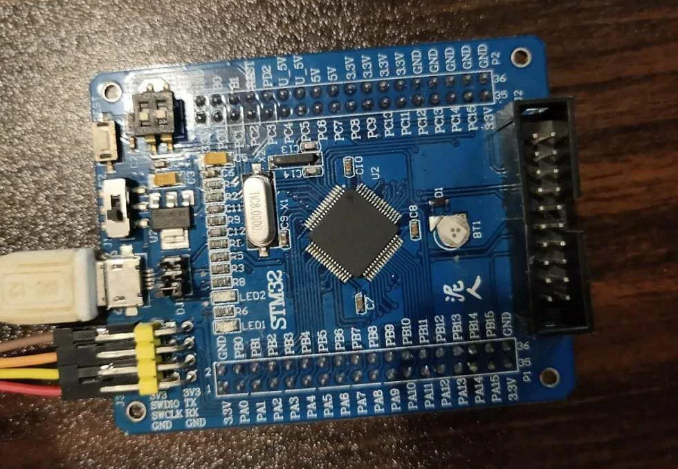
STM32F103RCT6
STM32 SCM在此我们已非常熟悉,不再赘述。
以下是我使用的STM32开发板:
应用架构
主代码如下:
#include "delay.h"
#include "sys.h"
#include "usart.h"
#include "hx711.h"
#define KEY_PEELED 0x0a
#define KEY_CLEAR 0x0b
#define KEY_UINT 0x0c
#define DISPLYER_ADDR0 0x0d
#define DISPLYER_ADDR1 0x0e
extern u8 USART_RX_END;
u8 data_send[8]= {0xA5, 0x5A, 0x05, 0x82, 0x00, 0x00, 0x00,0x00};
void UART1_Send_Array(u8 *send_array,unsigned char num)
{
u8 i=0;
while( USART_GetFlagStatus(USART1,USART_FLAG_TC)!= SET);
while(i<num)< span=""></num)<>
{
USART_SendData(USART1,send_array[i]);
while( USART_GetFlagStatus(USART1,USART_FLAG_TC)!= SET);
i++;
}
}
int main(void)
{
int cm,peeled;
u16 time=0;
delay_init();
NVIC_PriorityGroupConfig(NVIC_PriorityGroup_2);
uart_init(115200); //UART INIT
ADInit();//HX711 INIT
delay_ms(1000);
while(1)
{
delay_ms(5);
time++;
if(time>=60)
{
cm=11270-Get_Weight();//»ñȡʵÎïÖØÁ¿
//if(cm<=0)cm=0;
if(peeled)
{
cm=cm-peeled;
}
time=0;
data_send[5]=DISPLYER_ADDR0;
data_send[6] = cm >> 8;//hight
data_send[7] = cm & 0x00ff;//low
UART1_Send_Array(data_send,8); //Send display data
}
if(USART_RX_END)
{
switch (USART_RX_BUF[5])
{
case KEY_PEELED:
peeled=cm;
break;
case KEY_CLEAR:
peeled=0;
break;
case KEY_UINT:
break;
default:
USART_RX_END=0;
USART_RX_STA=0;
break;
}
USART_RX_END=0;
USART_RX_STA=0;
}
}
}
STONE 显示 UART 数据格式说明
以下指令表示将 00 04 写入数据存储区域的地址 0x0020:
0xA5 0x5A 0x05 0x82 0x01 0x33 0x00 0x04
0xA55A:数据帧头部
0x05:有效数据长度,从 0x82 开始
0x82:写寄存器指令
0x0133:写内存地址
0x0004:待写入的数据
只需在 Arduino 中编程,并将数据以这种格式发送至 STONE 串口触摸显示模块即可完成数据显示。
当用户按下串口屏串口显示屏上的按钮时,STM32 将接收 8 个字节的数据。我们只需确定第五个字节的数据即可判断用户按下了哪个按钮,然后编写代码让 MCU 执行相应的操作。