在本项目中,我将利用 STONE HMI 搭配 Arduino 控制 LED。在此过程中,Arduino 将从 STONE HMI 显示屏接收数据,根据按钮按下状态执行相应操作,并通过 AI-Thinker 工具查看数据以进行验证。
目录 表
[1] 描述
[2] 组件列表
[3] 软件/工具安装
[4] GUI设计与上传
[5] 工作原理与Arduino编程

1. STONE HMI描述
STONE Technologies是一家专业的HMI智能串口屏制造商。根据应用需求,STONE Technologies提供不同模块规格的智能串口屏。
2. 组件列表
[ 1] STONE HMI 显示屏 [STWI056WT/N-01]
[2] Arduino
[3] TTL 转 USB 转换器
[4] 9V-12V 电源
[5] USB 数据线
[6] LED
3. STONE Designer(图形用户界面设计软件)安装
在继续操作之前,我们需要安装 STONE Designer 和 USB 驱动程序,下面我们将介绍如何安装此软件。以下是 Drive 链接,您可以从中下载设计工具和 USB 驱动程序软件。
步骤1 : 打开此 Drive,您将看到如下所示的窗口,下载此软件并将其安装在您的计算机上。
Drive ink : https:/drive.google.com/drive/folders/1SbTuj9sqHLb9zV7pmEXOIyxWa9PAdOPH?usp=sharing
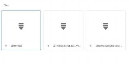
从这里下载第1个和第3个文件,因为第1个是GUI设计软件,第3个是USB
驱动程序。下载这些软件后,我们开始进行GUI设计。
4. GUI设计与上传
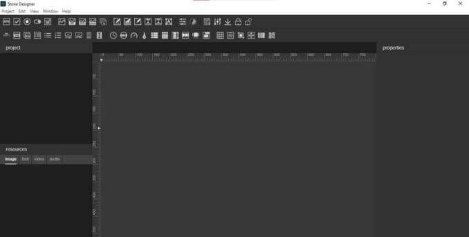
首先开始界面设计。安装完成后,点击STONE-Designer图标,随后设计软件将打开,您将看到如下界面(如图所示)。
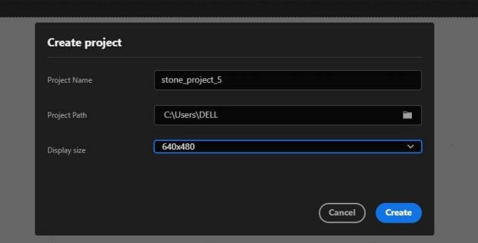
打开后,需创建新项目。点击顶部菜单中的“项目”,再选择“新建”,系统将提示输入项目名称及屏幕尺寸(请根据显示屏大小选择,此处使用640X480分辨率),并选择项目路径。填写完毕后点击“创建”。
完成上述步骤后,为项目选择背景图片,具体操作请按照图中所示步骤进行。
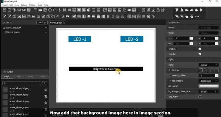
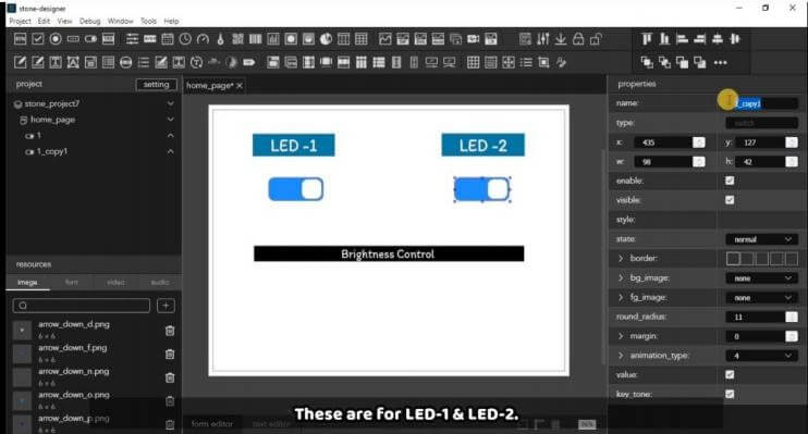
现在需要根据背景图片添加按钮和一个条形控制器。为此,只需在此处添加一个开关控件,并将其命名为“1”(可根据需要自定义名称)。同样,为第二个按钮添加控件并命名为“2”。您可以在下图中看到这两个按钮。
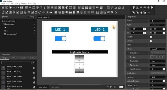
现在选择亮度条,为此需从控件中选择文本选择器。然后选择0-10的缩放范围,以便控制LED的亮度,随后可设置该控件的大小及其他参数。最终效果如下所示。
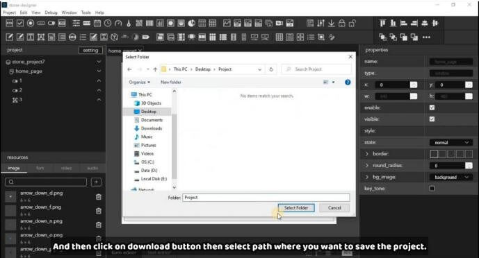
现在,根据项目 GUI 设计已完成,你需要点击顶部的“编译”按钮编译项目,然后点击“下载”按钮,并选择下载路径,如下图所示。
下一步是将 GUI-Design 上传到显示屏。为此,首先通过电源接口将显示屏连接至9-12伏电源
。随后将USB接口通过USB线连接至电脑与显示屏。连接后将呈现如下状态。


连接显示屏后,首先需通过GUI工具下载‘Default’文件夹。为此请进入调试菜单,点击下载,然后选择目标下载位置。
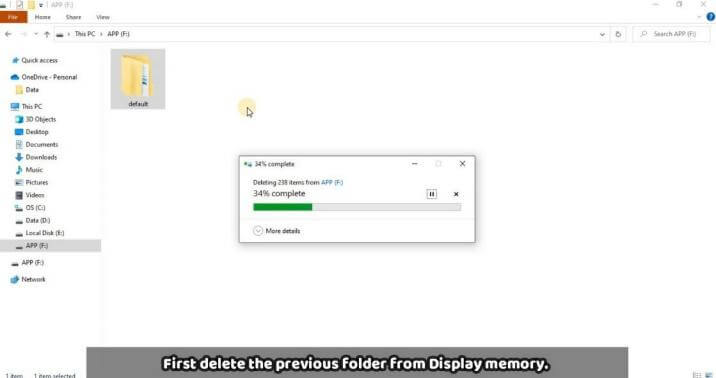
现在,我们在本地机器上有了Default文件夹,该文件夹将上传到显示屏内存中。为此,首先按照上图所示,通过USB-USB通信将HMI显示屏连接到电脑。在电脑上会出现一个存储设备,您需要删除其中第一个之前的Default文件夹,如下方图片所示。
之后,您可以将从GUI设计中复制的文件夹粘贴到此处。如下方图片所示。
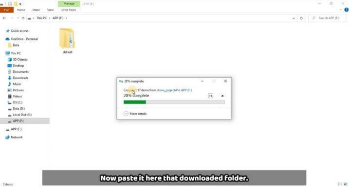
将默认文件夹粘贴到显示存储后,拔出显示屏的USB连接线并断开电源。
等待2-3秒后,重新连接显示屏的电源。此时您将看到我们设计的GUI界面。

现在GUI设计和上传部分已完成,接下来我们将查看代码及运行情况。
5. 工作原理及STONE HMI与Arduino编程
让我们了解代码的工作原理。
Arduino 代码
unsigned char Buffer[20];
#define LED1 2 /*Pin for LED- 1*/
#define LED2 3 / *PWM Pin for Brigh ness Controller LED-2 */
#define LED3 4 /*Pin for LED-3*/
void setup()
{
Serial.begin(115200);
pinMode(LED1,OUTPUT);
pinMode(LED2,OUTPUT);
pinMode(LED3,OUTPUT);
}
void loop()
{
if(Serial.available())
{
/* This loop will store whole frame in buffer array */
for(int i=0;i<=19;i++)
{
Buffer[i]= Serial.read();
}
/* Checking first index of the frame as it is 0X53 */
if(Buffer[0]==0X53)
{
/* Checking condition for LED- 1 [ON] at frame index 13 with value 0X97 */
if(Buffer[ 13]==0X97)
{
Serial.println("LED1_ON");
digitalWrite(LED1, HIGH);
}
/* Checking condition for LED- 1 [OFF] at frame index 13 with value 0X96 */
else if(Buffer[ 13]==0X96)
{
Serial.println("LED1_OFF");
digitalWrite(LED1, LOW);
}
/* Checking condition for LED-2 [ON] at frame index 13 with value 0XD3 */
else if(Buffer[ 13]==0XD3)
{
Serial.println("LED3_ON");
digitalWrite(LED3, HIGH);
}
/* Checking condition for LED-2 [OFF] at frame index 13 with value 0XD2 */
else if(Buffer[ 13]==0XD2)
{
Serial.println("LED3_OFF");
digitalWrite(LED3, LOW);
}
/* Store the value for brighness from the Frame at index 11 for LED-2*/
else if(Buffer[ 12]==0X3E)
{
int x=Buffer[ 11];
int Brightness=map(x,0,10,0,255);
Serial.print("LED2 Brightness :- ");
Serial.println(Brightness);
analogWrite(LED2,Brightness);
}
}
}
delay(10);
}
如代码所示,我们正在将20字节的数据存储到缓冲区中。此缓冲区的目的是存储来自显示屏的数据帧。根据数据帧的位置,我们在代码中检查条件,并根据数据帧的位置获取不同的值。
这些值可以在Ai-thinker工具中查看,以获取每个按钮的响应值。因此,您可以通过替换代码中的if-else判断值来创建自己的代码。虽然可能相同,但建议在Ai-thinker工具中验证一次。
让我们看看电路图,以便您能轻松连接。
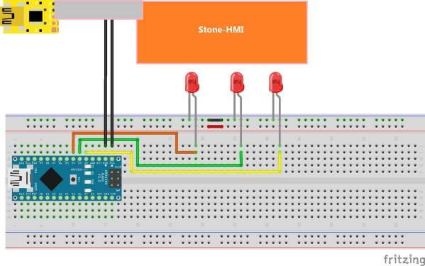
根据电路图,如果您想使用相同的引脚连接LED,请按图连接。这里可以看到,HMI显示屏通过TTL转换器连接,该转换器通常与显示屏一起提供。您需要将Tx和Rx连接到Arduino,以便与显示屏通信。
这样,您就完成了这个项目。您还可以参考这个项目的视频(STONE HMI与Arduino),该视频是基于此制作的。