- 摘要
在生产生活中,LED 炫光控制技术拥有无数应用场景,从大型到巨型户外串口屏,再到小型 LED 指示灯(如鼠标、键盘和钥匙扣),几乎随处可见。而树莓派Pico作为树莓派开源硬件家族的新成员,一经推出便引发热潮。2021年1月底,树莓派基金会发布重磅消息,正式将树莓派Pico推向微控制器领域。本文将利用微控制器树莓派Pico与STONE串口屏,开发一套RGB炫光控制解决方案。
- 实现的功能
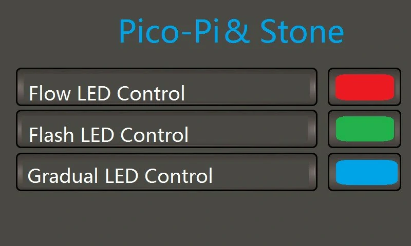
(A) RGB-LED 控制主界面
可跳转至三种 RGB LED 的工作控制选择界面。
(B) 流动灯光控制界面
- 红色流动灯光。
- 绿色流动灯光。
- 蓝色流动灯光。
(C) 闪烁灯光控制界面
- 500 毫秒闪烁。
- 1000 毫秒闪烁。
- 1500 毫秒闪烁。
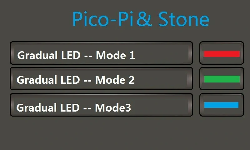
(D) 渐变光控制界面
3种渐变模式。
III. 系统原理与组成
(A) 系统原理
通过串口屏,系统收集操作员的指令并通过串口发送至Raspberry Pi Pico。Raspberry Pi Pico分析指令并通过WS2812B兼容的定时控制信号控制灯光设置。
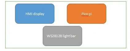
(B) 系统组成
系统主要由串口屏、Raspberry Pi Pico、WS2812B灯条板四部分组成。
- 树莓派 Pico 与 STONE LCD 显示系统硬件设计
(A) STONE串口屏
- “RGB LED 彩色灯光控制” 硬件设计
采用北京STONE科技有限公司生产的 STONE串口屏,型号为 STVC070WT-01,集成了串口屏和触摸控制器。
(1)STVC070WT-01产品特性
- 可由任何 MCU 控制。
- 显示图片/文字/曲线。
- 65536色串口屏。
- 带/不带触摸屏。
- RS232/RS485/TTL UART接口和USB端口。
- 宽电压范围。
(2) 接口
- 电源接口。
- 由12V 1A电源适配器供电。
- 通信接口
- 通过RS232串口进行外部通信,波特率为115200bps。
(B) WS2812灯条控制板
- 灯条控制面板
采用Raspberry Pi生态系统的新成员,Raspberry Pi Pico。
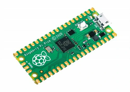
树莓派 Pico 微控制器
树莓派 Pico 基于基金会的新芯片 RP2040 微控制器设计。以下是其参数。
https://www.raspberrypi.org/products/raspberry-pi-pico/
- 双核 32 位 ARM Cortex-M0+ 处理器
- 运行频率为 48MHz,但可超频至 133MHz
- 30 个通用输入输出引脚(26 个外露)
- 支持 USB 主机或设备模式
- 8 个可编程输入输出(PIO)状态机
- RP2040 支持最高 16MB 的片外闪存,但 Raspberry Pi Pico 仅支持 4MB。
- 三个 12 位 ADC 引脚。
- UART、SPI、IIC 功能。
- 系统软件设计
(A) RGB LED 炫光控制主界面
Raspberry Pi Pico 和 STONE串口屏的开发过程
- 创建项目并加载所需图片到项目中。 raspberry pi pico 教程
- 在此制作背景图片,通过 Ico 显示楼层及上下信息。
- 使用 TOOL-2019 控件创建动态关联关系;主要控件包括:“动画图标”、“变量图标”;
- 进行软件模拟与编译以生成可执行文件。
- 串口屏通过调试工具连接至电脑,并将可执行文件下载至屏幕。
在此,在界面中添加按钮功能,将效果设置为下一章键触发图片,转到对应的设置界面。
控制
通过使用“通过使用“可变图标”、“按钮键值返回”以及控制组件的音频属性,实现动态灯光控制功能。返及
(1)STONETOOLBox图形用户界面设计软件SO OL户界面设计软件
首先,我们创建基础地图,并为按钮触发器制作对应的动作效果地图,如下图所示。先建图
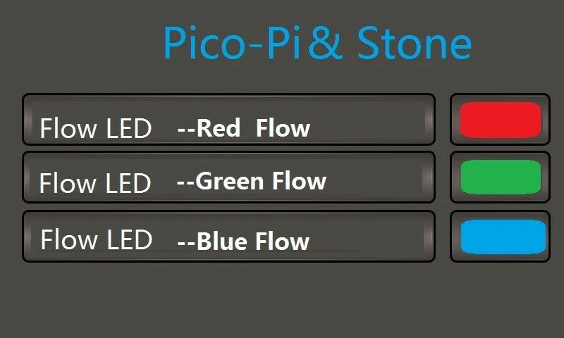
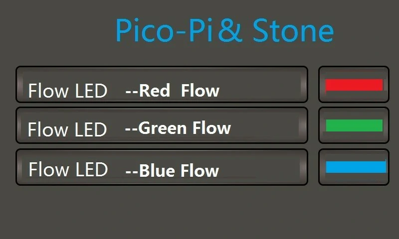
- 红色流程选定命令:A5 5A 06 83 00 86 01 00 00。
- 绿色流程选定命令:A5 5A 06 83 00 87 01 00 00。
- 蓝色流程选定命令:A5 5A 06 83 00 88 01 00 00。
(2) Raspberry Pi Pico 控制台软件设计
通过串口从 LCD 显示屏接收命令,解析并调用 WS2812b 函数驱动 LED 执行对应操作。
# 灯带状态控制,模式=1-3为三色跑动灯光
# 模式=4-6为间隔闪烁,500ms、1s、1.5s
# 模式=7-9为三色渐变
if mode==0x01 or mode==0x02 or mode==0x03:
if no < 7 :
no = no + 1
else: no = 0
time.sleep_ms(500)
if mode == 0x01:
np.fill(0,0,0)
np.set_pixel(no,5,0,0)
np.show()
time.sleep_ms(200)
elif mode == 0x02:
np.fill(0,0,0)
np.set_pixel(no, 0, 5, 0)
np.show()
time.sleep_ms(200)
elif mode == 0x03:
np.fill(0, 0, 0)
np.set_pixel(no, 0, 0, 5)
np.show()
time.sleep_ms(200)
(C) RGB LED 闪烁灯光控制
STONE LCD 显示屏通过使用“可变图标”、“按钮键值返回”以及控制项的音频属性,实现灯光控制功能。
(1) STONE 工具箱 软件设计
首先,我们制作基础地图,并为按钮按下操作制作对应的动作效果地图,如图所示。
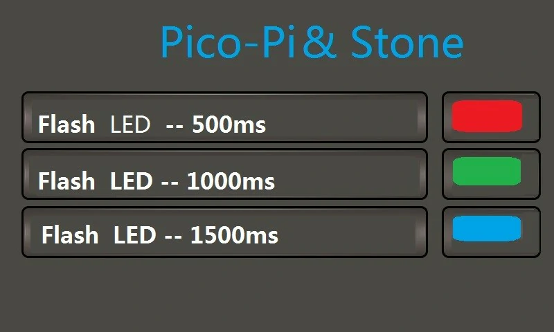
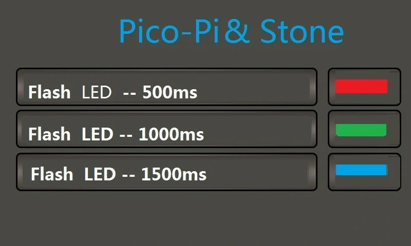
- 500毫秒闪烁选定命令:A5 5A 06 83 00 89 01 00 00.
- 1000毫秒闪烁选定命令:A5 5A 06 83 00 8A 01 00 00.
- 1500毫秒闪烁选定命令:A5 5A 06 83 00 8B 01 00 00。
(2) Raspberry Pi Pico 控制台软件设计
通过串口从LCD显示屏接收命令,解析并调用WS2812b函数驱动LED执行对应操作。
# 灯带状态控制,模式=4-6为间隔闪烁,500ms 1s 1.5s
# 灯带状态控制,模式=4-6为间歇闪烁,500ms 1s 1.5s
elif mode == 0x04:
np.fill(5,0,0)
np.show()
time.sleep_ms(500)
np.fill(0,0,0)
np.show()
time.sleep_ms(500)
elif mode == 0x05:
np.fill(0,5,0)
np.show()
time.sleep_ms(1000)
np.fill(0,0,0)
np.show()
time.sleep_ms(1000)
elif mode == 0x06:
np.fill(0,0,5)
np.show()
time.sleep_ms(1500)
np.fill(0,0,0)
np.show()
time.sleep_ms(1500)
(D) RGB LED 渐变灯光控制
STONE LCD 显示屏通过使用“可变图标”、“按钮键值返回”以及控制项的音频属性,实现灯光控制功能。
(1) STONE 软件图形用户界面设计
首先,我们制作基础地图,并为按钮按下操作制作对应的动作效果图,如图所示。
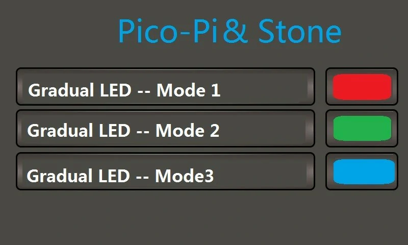
- 第二个淡出命令已选中:A5 5A 06 83 00 8D 01 00 00。
- 第三个淡入命令:A5 5A 06 83 00 8E 01 00 00。
(2) Raspberry Pi Pico 控制台软件设计
通过串口从 串口屏接收命令,解析并调用 WS2812b 函数驱动 LED 执行相应操作。
# 灯带状态控制,模式为 7-9 表示三色渐变
elif mode == 0x07:
np.set_pixel_line_gradient(0,7,1,1,1,30,10,5)
np.show()
elif mode == 0x08:
np.set_pixel_line_gradient(0,7,1,1,1,5,10,30)
np.show()
elif mode == 0x09:
np.set_pixel_line_gradient(0,7,1,1,1,10,30,5)
np.show()
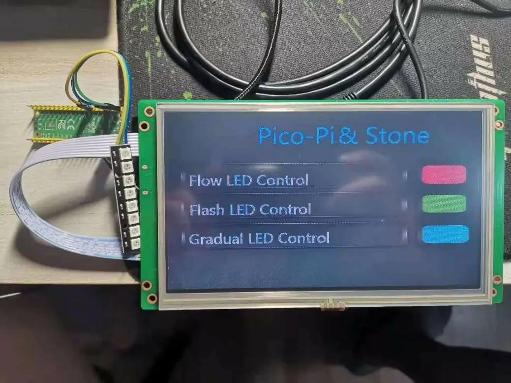
VI.系统运行效果测试
树莓派Pico与STONE串口屏炫光控制系统物理演示效果如图所示。
VII. 未来展望
本案例采用 Raspberry Pi Pico 和 STONE 串口屏构建 RGB 炫彩灯光控制单元,可扩展至控制 8 引脚的 256 颗灯珠,形成 32×64 三色点阵屏。