目录
- 描述
- 组件列表
- 软件/工具安装
- 树莓派图形界面设计与上传
- 工作原理与树莓派编程
[1] 描述
STONE Technologies 是专业生产智能串口屏的制造商,主要应用于人机界面(HMI)领域。根据不同应用需求,STONE Technologies 提供工业级、高端及家用智能串口屏,涵盖多种尺寸规格。
在本项目中,我将利用 STONE串口屏和 Raspberry Pi 图形界面设计控制 LED。命令数据通过显示屏发送至 Raspberry Pi,以帧形式传输,因为显示屏以帧形式发送数据并接收 HEX 代码格式的帧数据。若需了解数据帧结构及工作原理,本项目采用 STWI056WT-01 型号。您可从此处下载数据手册。
[2] 组件列表
- STONE-HMI显示屏 [ STWI056WT-01 ]
- Raspberry Pi
- TTL转USB转换器
- 9V-12V电源适配器
- USB数据线
- 发光二极管
[3] 软件 / STONE Designer 安装
在继续之前,我们需要安装 STONE Designer 和 USB 驱动程序,让我们看看如何安装此软件。以下是驱动程序链接,您可以从中下载 Designer 工具和 USB 驱动程序软件。
步骤 1:- 访问此驱动程序,您将看到如下所示的窗口,下载此软件并将其安装到计算机中。
https://drive.google.com/drive/folders/1SbTuj9sqHLb9zV7pmEXOIyxWa9PAdOPH?usp=sharing
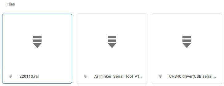
从这里下载第一个和第三个文件,因为第一个文件是用于GUI-Designer工具,第三个文件是用于USB驱动程序。下载这些软件后,让我们开始进行GUI设计。
[4] GUI设计与上传
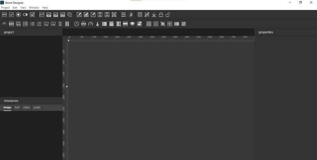
首先进行界面设计。安装完成后,点击STONE-Designer图标,打开设计软件后将看到如下界面。
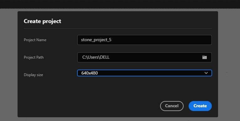
打开后,需为本项目创建新项目,从顶部菜单选择“项目”,然后选择“新建”,系统将提示您填写如下信息:输入项目名称并根据显示屏尺寸选择屏幕分辨率(此处使用640×480分辨率),填写所有信息后选择项目路径并点击“创建”。
完成上述步骤后,选择项目背景图片,如图所示。
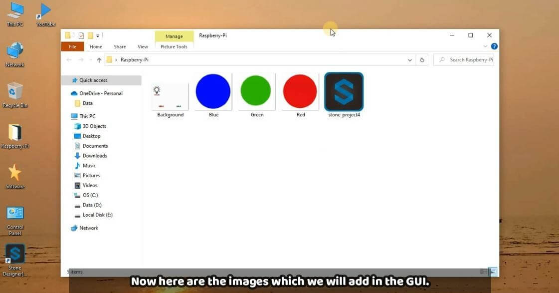
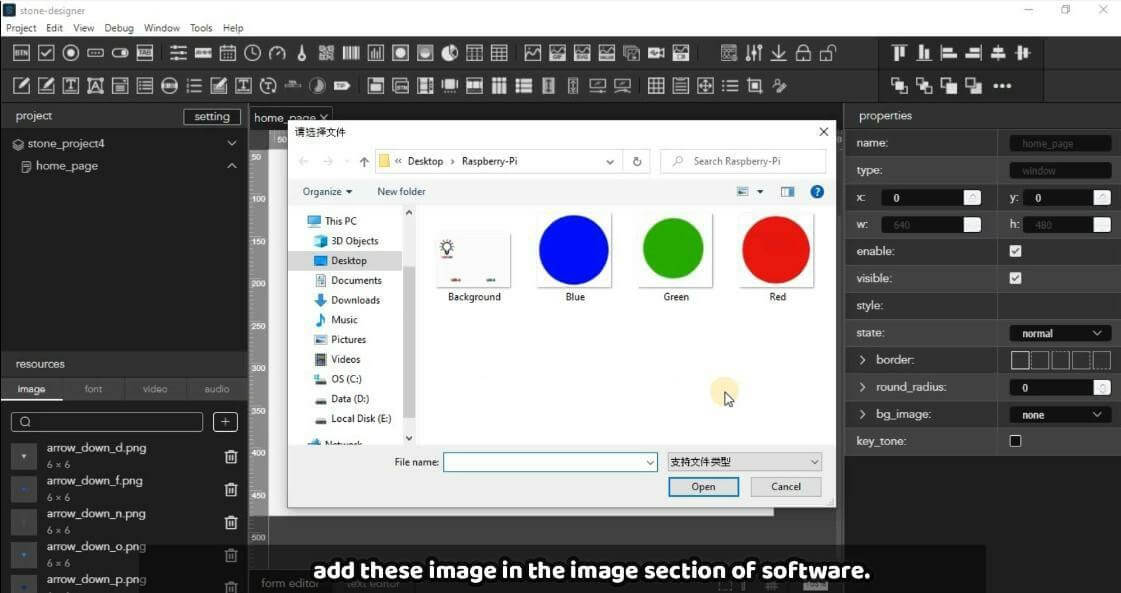
步骤1: – 从资源中选择“图像”以上传背景图片。后续处理中将使用其他图片作为按钮,这些图片如下所示,您可根据需要自行设计。
步骤2: – 点击下图中的“+”按钮,将这些图片添加到GUI工具中。
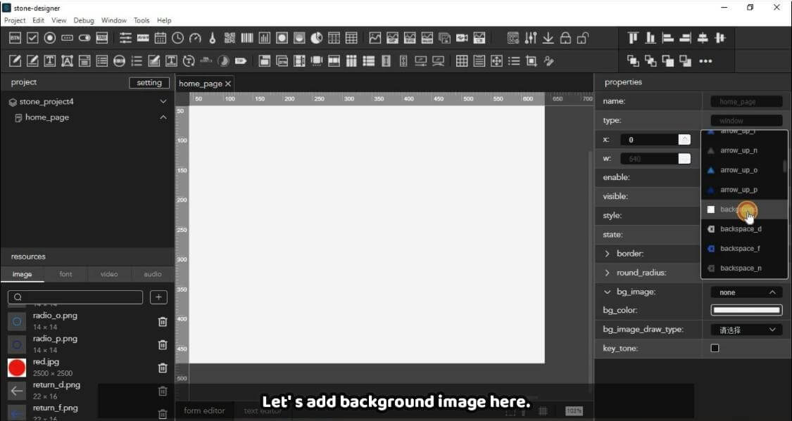
步骤 3: – 现在点击空白屏幕添加第一张背景图片,右侧会出现更多选项(如图所示)。从中选择“背景图片”选项,并选择之前添加的图片(如图所示)。
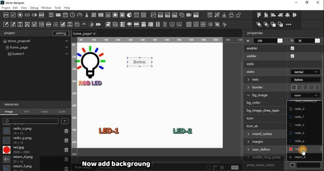
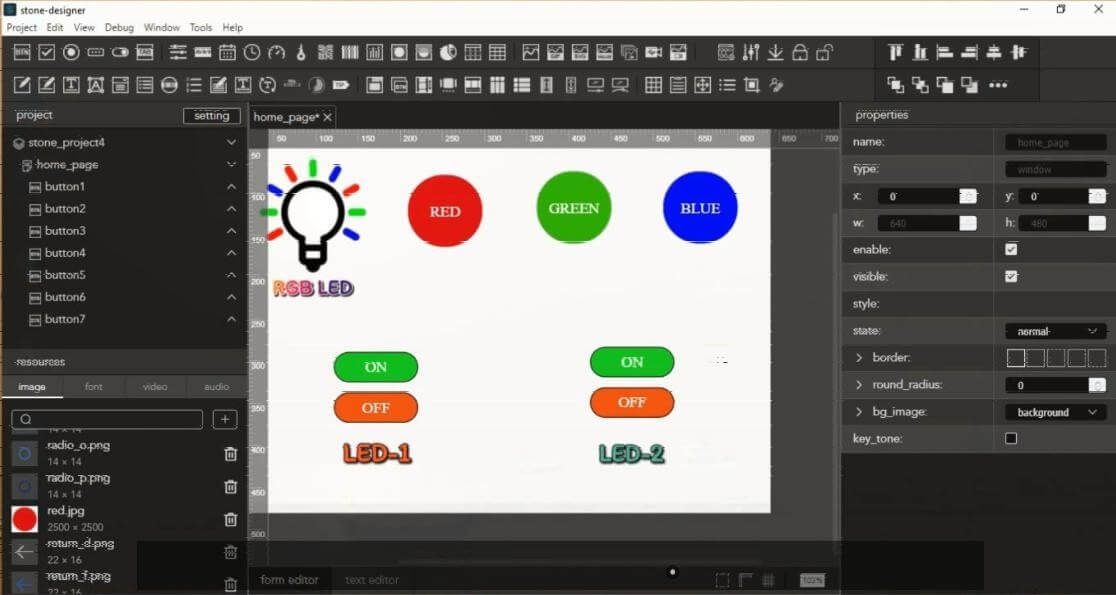
步骤 4:现在依次添加 RGB 按钮。如图所示,第一个按钮已添加,首先对其进行修改,然后依次对其他按钮进行相同操作。
现在选择我们添加的第一个按钮,进入其属性设置(位于右侧,如图所示)。
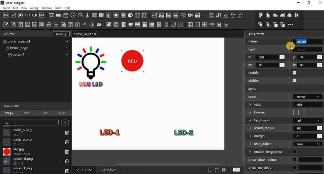
步骤5:- 在此选择背景图像为红色,因为此按钮对应红色LED。同时设置其他参数如文字颜色和大小。完成第一个按钮的设置后,可按照相同步骤处理其他按钮。
但添加所有按钮后,需记录下它们的名称(如下图所示高亮部分)。请为每个按钮依次命名,如button1、button2等。此命名规则在后续编码部分会用到,请务必记住。
最终界面将呈现如下效果,此时GUI设计已完成,可继续后续操作。
步骤6:此步骤用于将GUI设计上传至显示屏。首先通过电源接口将显示屏连接至9-12伏电源。随后将USB接口连接至显示屏与电脑之间的USB接口。连接后将呈现如下状态。

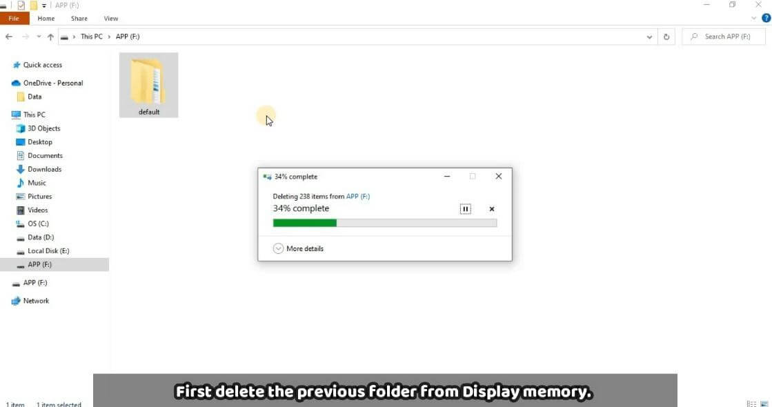
连接显示屏后,首先需通过GUI工具下载‘Default’文件夹。为此,请转到调试,然后点击下载,选择要下载的位置。

现在,本地机器上的默认文件夹将上传到显示屏内存中。为此,请按照上图所示,通过USB与电脑进行USB通信连接显示屏。在电脑上会出现一个存储设备,首先删除其中之前存在的默认文件夹,如下图所示。
之后,将从 GUI 设计中复制的文件夹粘贴到此处,如图所示。
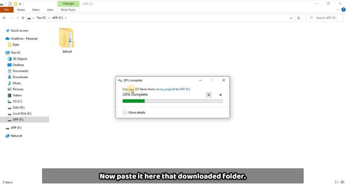
将默认文件夹粘贴到显示存储后,拔出显示器的 USB 接口并断开电源供应,等待 2-3 秒后重新连接电源。此时将显示我们设计的 GUI 界面。
现在,GUI设计和上传部分已完成,接下来是检查代码并验证其功能。
[5] 工作原理及树莓派GUI编码
首先通过VNC服务器连接树莓派,或根据需要直接连接显示屏。下方提供两个代码。第一个用于测试所有创建的按钮,第二个是包含I/O设置和逻辑的完整代码。
测试代码:
import serial
serialcomm = serial.Serial(‘/dev/ttyUSB0’, 115200) while True:
l=serialcomm.read(size=20) q=l[7:14]
Print(q)
此测试代码的目的是检查所有按钮。为此,您需要先将树莓派的USB-0接口连接到显示屏的TTL接口,然后将以下代码复制到树莓派的Thonny中,并点击运行按钮进行测试。

点击显示屏上的任意按钮,将显示我们之前在代码中赋予的按钮名称。按下显示屏上的Button-1后,我们会得到输出字符串button1,因为我们对整个字符串进行了切片,从而从显示屏获取了对应部分。
l=serialcomm.read(size=20) q=l[7:14]
在测试代码中,这些代码行中,l 是接收来自显示屏的帧的变量,大小为 20,然后 q 存储了根据需求切片后的值。
在完整代码中,我们根据每个按钮的逻辑进行了相应设置。以下逻辑示例为按下按钮6时,LED2高电平(亮起),按下按钮7时,LED2低电平(熄灭)。其他LED的逻辑同样适用。
elif(q==b’button6′):
GPIO.output(led2,GPIO.HIGH)
elif(q==b’button7′):
GPIO.output(led2,GPIO.LOW)
Raspberry Pi GUI 完整代码:
import RPi.GPIO as GPIO GPIO.setmode(GPIO.BCM) GPIO.setwarnings(False) led1 = 26
led2 = 19
red_led= 13
green_led= 6
blue_led= 5 status1=0 status2=0
GPIO.setup(red_led,GPIO.OUT) GPIO.setup(green_led,GPIO.OUT) GPIO.setup(blue_led,GPIO.OUT) GPIO.setup(led1,GPIO.OUT) GPIO.setup(led2,GPIO.OUT) GPIO.output(red_led,GPIO.LOW) GPIO.output(green_led,GPIO.LOW) GPIO.output(blue_led,GPIO.LOW) GPIO.output(led1,GPIO.LOW) GPIO.output(led2,GPIO.LOW) ######################
import serial
serialcomm = serial.Serial(‘/dev/ttyUSB0′, 115200)
while True: l=serialcomm.read(size=20) q=l[7:14]
if(q==b’button1′): print(q)
GPIO.output(red_led,GPIO.HIGH) GPIO.output(green_led,GPIO.LOW) GPIO.output(blue_led,GPIO.LOW)
elif(q==b’button2′): GPIO.output(green_led,GPIO.HIGH) GPIO.output(red_led,GPIO.LOW) GPIO.output(blue_led,GPIO.LOW)
elif(q==b’button3′): GPIO.output(blue_led,GPIO.HIGH) GPIO.output(red_led,GPIO.LOW) GPIO.output(green_led,GPIO.LOW)
elif(q==b’button4’): GPIO.output(led1,GPIO.HIGH)
elif(q==b’button5′): GPIO.output(led1,GPIO.LOW)
elif(q==b’button6′): GPIO.output(led2,GPIO.HIGH)
elif(q==b’button7′): GPIO.output(led2,GPIO.LOW)
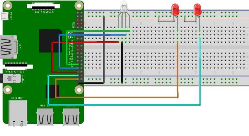
现在我们已经理解了代码的逻辑,让我们在树莓派上运行第二个代码,这是完整的代码,但在连接电路之前,请先按照下面的电路图进行连接。
电路图:
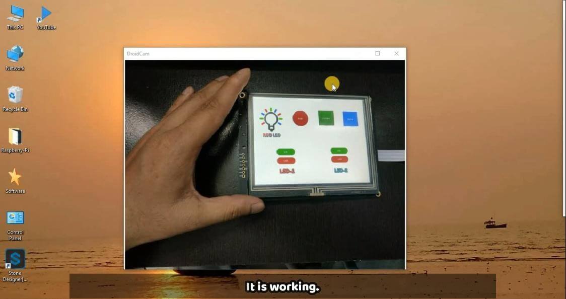
树莓派图形界面输出。
现在我们已经完成了整个项目,你可以测试你的项目,最终的设置将如下所示。