OV7670摄像头模块与STONE串口屏的连接,主要功能
- 显示屏实时显示摄像头采集的图像
- 点击按钮拍摄图像并保存至TF卡
- 切换颜色与灰度
- 分辨率可切换 (240*320, 240*240, 160*160, 80*80)
- 可切换至图片查看模式
- 可浏览上一张图片
- 可浏览下一张图片
在开始本项目之前,让我们先看看需要哪些硬件模块。
- STONE 7英寸 800*480分辨率串口显示模块
- STM32F103ZE开发板
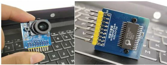
- OV7670摄像头模块
- 少量相关线缆
STM32F103ZE开发板
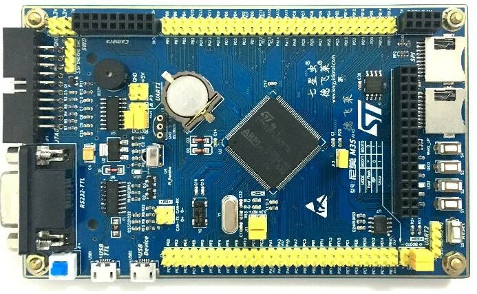
该开发板集成了多项功能
-
- Cortex-M3核心芯片,STM32F103ZET6,
- 144针脚
- 外部晶体振荡器8M,时钟晶体振荡器32768Hz
- 标准20针插座,JTAG接口,用于下载调试程序如Jlink、Ulink和st-link
- 标准4针插座, SWD接口,采用2线通信方式进行调试和程序下载
- 所有I/O端口均用于插针,便于实验扩展
- USB-TTL串口转换电路,实现USB接口的串口通信
- 自动下载适配电路,通过串口下载无需频繁切换,一键即可完成下载
- MAX232转换电路,适用于外部串行线路
- 集成红外接收器,用户可实现远程红外接收功能
- DS18B20插座,直接插入芯片实现数字温度测量功能
- 带时钟备份电池,保持时钟和重要信息在断电时不丢失
- EEPROM芯片24C02,用于存储常用用户信息并采用IIC通信
- FLASH芯片W25Q64,8M内存,可存储图片、系统数据及其他信息
- SPI模式SD卡座,支持TF卡,PI通信
- SDIO模式SD卡座, TF卡,专用SDIO接口,高速稳定。
- RF24L01插座用于无线通信测试(至少需要2台设备)
- 3路普通按键输入功能,人机交互界面
- 1路唤醒按钮,用于从低功耗或待机模式唤醒
- 2路用户LED指示灯,显示基本状态和操作指令
- 1个USB设备接口,用于调试USB设备功能,如读卡器、USB串口功能
- TFT彩色屏幕LCD接口,包括触摸屏接口,可直接插入到支持屏幕中
- 摄像头预留接口,支持摄像头模块实现视频展示功能
- 1个蜂鸣器
- 1个触摸按钮功能
- 自恢复保险丝,保护计算机免受损坏
- 复位按钮
- 电源指示灯
- 选择插入引脚
- 选择带有VREF参考电压的引脚
- CAN、USB开关引脚
- 3.3V外部电源供电引脚插入
- 5V外部扩展电源供电引脚插入
但实际上,我们仅使用其摄像头接口和串口,以及TF卡接口
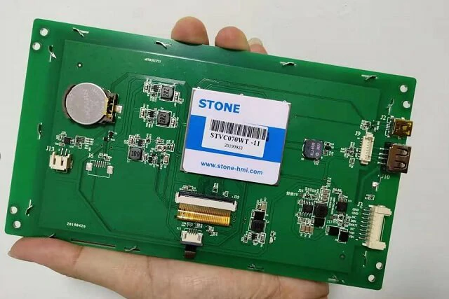
STONE串口屏
STONE STVC070WT-01是一款7英寸显示模块,分辨率为800×480。该显示模块可通过STONE官方网站或STONE在线购物平台链接购买。
STONE stvc070wt-01 的通信模式为 UART-RS232 和 UART-TTL。在本项目中,我使用了 UART-TTL 通信模式。
显示模块的开发方式较为简单,MCU只需通过UART向STONE 发送指令, 显示模块内容即可实现控制。当用户触摸 STONE 显示屏时,显示模块会通过 UART 将相关指令发送至 MCU,随后 MCU 控制对应设备(如电机旋转、灯光开关等)。
7 英寸 STONE STVC070WT-01
制造商提供的材料如下:

主包装清单
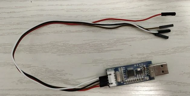
- 传输连接线
- USB-TTL适配器板
- USB闪存盘(含开发资料)
- Micro USB 数据线
- USB 传输板
- STONE STVC070WT-01 显示模块
- 12V 电源适配器
STONE串口屏规格
STVC070WT-01 是一款 TFT 显示屏与触摸控制器。它集成了处理器、控制程序、驱动程序、闪存、RS232/RS485/TTL 接口、触摸屏、电源等组件, 是一款强大的显示系统
操作系统简单,可由任何单片微控制器控制。STVC070WT-01 可实现所有基本功能,如文本显示、图像显示、曲线显示、触摸功能、视频和音频功能等。
- 内置 Cortex CPU 和驱动程序
- 可由任何单片微控制器控制
- 显示图片/文本/曲线
- 65536 色 TFT 显示屏
- – 支持触摸操作
- RS232/ RS485/ TTL UART 接口和 USB 端口
- 宽电压范围
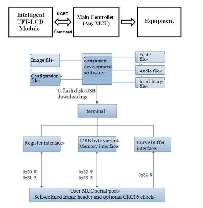
STVC070WT-01 显示模块控制原理
TFT-LCD 模块通过命令(十六进制)与 MCU 通信,MCU 将根据接收到的命令进行工作。
完成 STONE串口屏的固件开发需要三个步骤
使用STONE的TFT-LCD模块仅需3个步骤:
- 设计一套人机交互界面(UI)。
- UART-TTL 直接连接至客户的 MCU。
- 编写一个简单程序,通过 MCU 发送命令控制 TFT-LCD 模块。(十六进制代码)。
串口屏的串行命令帧由五个数据块组成,所有数据均以十六进制格式表示。数据传输方式为从MSB到LSB。例如,对于0x1234,首先发送0x12,然后发送0x34。
UI 图片设计计
用户使用 Photoshop 或其他软件设计 UI

我设计的界面如下:
第一张图片是主屏幕图片,第二张图片是按下按钮时的效果。
使用 TOOL2019 软件生成 LCD 模块配置文件
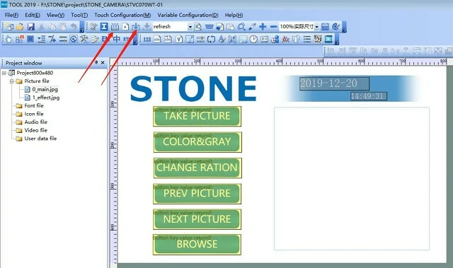
点击箭头按钮生成配置文件,然后将配置文件下载到显示模块以显示我们设计的UI界面。生成配置文件,然后将配置文件下载到显示模块以显示我们设计的UI界面。
此部分内容和教程的详细说明在此不再赘述,您可以前往STONE官网下载非常详细的教程。
此外,我们还需要设计一个与按钮按下效果相同的图片。只需将按钮位置的颜色更改为下表所示。

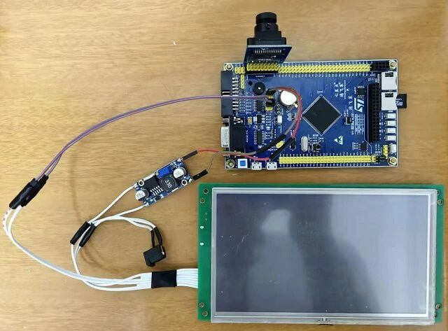
STM32 MCU与VO7670的接线与焊接MCU与VO7670的接线与焊接
在前面的内容中,我介绍了STONE STVC070WT-01的相关开发操作。在接下来的内容中,我将重点介绍STM32 MCU与VO7670摄像头。在开始之前,让我们先看看项目硬件部分的连接方式。
STONE项目完整接线图
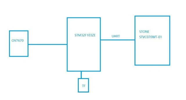
OV7670 模块 — STM32 开发板:
OV_D0 ~ D7 — — — — — — — — — — – PC0 ~ 7
OV_SCL — — — — — — — — — — — — PD3
OV_SDA — — — — — — — — — — — — PG13
OV_VSYNC — — — — — — — — — — — — PA8
FIFO_RRST — — — — — — — — — — – PG14
FIFO_OE — — — — — — — — — — – PG15
FIFO_WRST — — — — — — — — — — — — PD6
FIFO_WEN — — — — — — — — — — — — PB3
FIFO_RCLK — — — — — — — — — — — — PB4
电源适配器为12V,需为STONE stvc070wt-01显示模块供电,并通过DC-DC降压模块将电压降至5V为MCU模块和OV7670供电。
项目所用配件
主要配件包括:
- STM32F103ZE开发板
- DC-DC降压模块
- UART 切换
由于 STONE STVC070WT-01 的默认通信模式为 UART-TTL,因此无需 RS232 接口进行连接切换,可移除 RS232 接口:

焊接
通过焊接这些部件,效果如下:
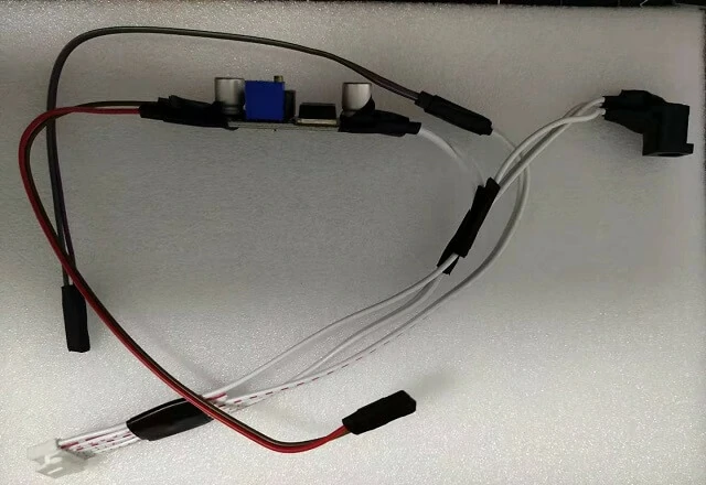
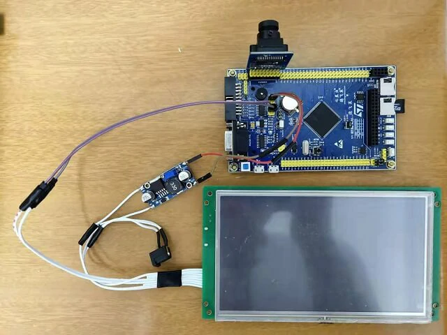
当该部分准备就绪后,即可为 MCU 编写程序。
OV7670 摄像头模块 摄像头模块
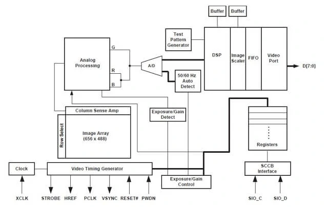
OV7670 功能块图
OV7670 是一种图像传感器,工作温度为 -30℃-70℃,模拟电压为 2.5-3.0V,光敏阵列为 640×480,功耗为 60mW/15fps。待机功耗小于 20μA。
体积小,工作电压低,具备单个VGA摄像头和图像处理器的所有功能。通过SCCB总线控制,可输入全帧、子采样、窗口等多种分辨率的8位图像数据。该产品的VGA图像最高可达30帧/秒。用户可完全控制图像质量、数据格式和传输方式。所有图像处理功能,包括伽马曲线、白平衡、饱和度、色度等,均可通过SCCB接口进行编程。通过减少或消除固定图案噪声、尾部支持、漂移等光学或电子缺陷,可提升图像质量,获得清晰稳定的彩色图像。漂移等光学或电子缺陷,可提升图像质量,获得清晰稳定的彩色图像。
OV7670是OV(OmniVision)生产的1/6英寸CMOS VGA图像传感器。该传感器
该设备体积小巧,工作电压低,集成了单个VGA摄像头和图像处理器的所有功能。通过SCCB总线控制,可输出全帧、子采样、窗口等多种分辨率的8位图像数据。产品VGA图像最高可达30帧每秒。用户可完全控制图像质量、数据格式及传输。所有图像处理过程,包括伽马曲线、白平衡、亮度、色彩等,均可通过SCCB接口进行编程。OmniVision图像传感器采用独特传感器技术,通过减少或消除固定图案噪声、尾部支持、漂移等光学或电子缺陷,提升图像质量,获得清晰稳定的彩色图像。行编程。OmniVision图像传感器采用独特传感器技术,通过减少或消除固定图案噪声、尾部支持、漂移等光学或电子缺陷,提升图像质量,获得清晰稳定的彩色图像。
OV7670的特点包括:
- 高灵敏度,低电压,适用于嵌入式应用
- 标准SCCB接口,兼容IIC接口
- 支持 VGA、CIF 以及从 CIF 到 40×30 的所有尺寸持 VGA、CIF 以及从 CIF 到 40×30 的所有尺寸
- 支持自动曝光控制、自动增益控制、自动白平衡和自动消除光线条纹
- 闪光灯支持灯支持
- 支持图像缩放
OV7670传感器包含以下功能模块。
- 图像阵列
OV7670总像素为656×488,其中640×480为有效像素(即有效像素为30W)。
- 视频定时发生器
序列发生器具有以下功能:全序列控制和帧率生成(以7种不同格式输出)、内部信号发生器535及分配、帧率定时、自动曝光控制,以及外部定时输出(VSYNC、HREF/HSYNC 和 PCLK)。制和帧率生成(以7种不同格式输出)、内部信号发生器535及分配、帧率定时、自动曝光控制,以及外部定时输出(VSYNC、HREF/HSYNC 和 PCLK)。
- 模拟信号处理
模拟信号处理模块负责所有模拟功能,包括自动增益控制(AGC)和自动白平衡(AWB)。B)。
- 模数转换(A/D)
原始信号经过模拟处理模块后,通过G和BR通道进入10位A/D转换器。
A/D转换器以12MHz的采样频率运行,与像素频率完全同步(转换频率与帧率相关)。
A/D 范围乘积与 A/D 范围控制共同设定 A/D 范围和最大值,允许用户根据应用需求调整图像亮度。
接下来,介绍OV7670的图像数据输出格式。首先,简要说明一些定义:7670的图像数据输出格式。首先,简要说明一些定义:
VGA,即分辨率为640×480的输出模式;
QVGA,分辨率为320×240的输出格式,本章所需的格式。
QQVGA,即分辨率为160×120的输出格式;格式;
PCLK,即像素时钟,一个PCLK时钟输出一个像素(或半个像素)。
VSYNC,帧同步信号。HREF/HSYNC,行同步信号。
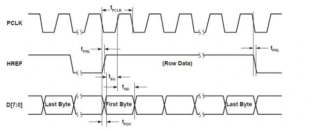
OV7670的图像数据输出(通过 D[7:0])由 PCLK、VSYNC 和 HREF/HSYNC 控制。
如下所示。首先,查看行输出的时序,如图所示:
如上图所示,当 HREF 为高电平时输出图像数据,当每个 PCLK
时钟高电平时,输出一个字节的数据。例如,我们使用 VGA 时序,RGB565 格式输出,每 2 字节构成一个像素颜色(高字节在前,低字节在后),因此每行输出总共需要 640*2 个 PCLK 周期,输出 640*2 个字节。
帧时序(VGA 模式) :
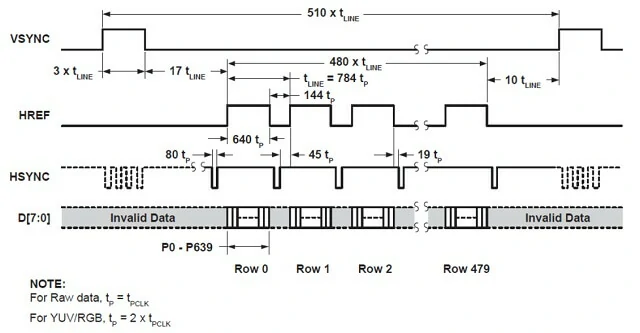
实际上这是同一引脚的信号,但在不同情况下以不同方式使用,本章中使用 HREF。
由于 OV7670 的像素时钟(PCLK)可达 24MHz,我们使用 STM32F103ZET6 的 IO 端口直接捕获,
这非常困难且占用大量CPU资源
(IO端口可通过降低PCLK输出频率实现捕获,但不推荐)。困难且占用大量CPU资源 (IO端口可通过降低PCLK输出频率实现捕获,但不推荐)。
本项目采用RGB565模式,捕获的图像数据为原始RGB数据,随后通过UART传输至STONE串口屏。
OV7670摄像头模块驱动程序
u8 OV7670_Init(void){u8 temp;u16 i=0;GPIO_InitTypeDef GPIO_InitStructure;RCC_APB2PeriphClockCmd(RCC_APB2Periph_GPIOA|RCC_APB2Periph_GPIOB|RCC_APB2Periph_GPIOC|RCC_APB2Periph_GPIOD|RCC_APB2Periph_GPIOG, ENABLE);GPIO_InitStructure.GPIO_Pin = GPIO_Pin_8;GPIO_InitStructure.GPIO_Mode = GPIO_Mode_IPU;GPIO_InitStructure.GPIO_Speed = GPIO_Speed_50MHz;GPIO_Init(GPIOA, &GPIO_InitStructure);GPIO_InitStructure.GPIO_Pin = GPIO_Pin_3|GPIO_Pin_4;GPIO_InitStructure.GPIO_Mode = GPIO_Mode_Out_PP;GPIO_Init(GPIOB, &GPIO_InitStructure);GPIO_SetBits(GPIOB,GPIO_Pin_3|GPIO_Pin_4);GPIO_InitStructure.GPIO_Pin = 0xff;GPIO_InitStructure.GPIO_Mode = GPIO_Mode_IPU;GPIO_Init(GPIOC, &GPIO_InitStructure);GPIO_InitStructure.GPIO_Pin = GPIO_Pin_6;GPIO_InitStructure.GPIO_Mode = GPIO_Mode_Out_PP;GPIO_Init(GPIOD, &GPIO_InitStructure);GPIO_SetBits(GPIOD,GPIO_Pin_6);GPIO_InitStructure.GPIO_Pin = GPIO_Pin_14|GPIO_Pin_15;GPIO_InitStructure.GPIO_Mode = GPIO_Mode_Out_PP;GPIO_Init(GPIOG, &GPIO_InitStructure);GPIO_SetBits(GPIOG,GPIO_Pin_14|GPIO_Pin_15);GPIO_PinRemapConfig(GPIO_Remap_SWJ_JTAGDisable,ENABLE); //SWDSCCB_Init(); //³õʼ»¯SCCB µÄIO¿Úif(SCCB_WR_Reg(0x12,0x80))return 1; //¸´Î»SCCBdelay_ms(50);temp=SCCB_RD_Reg(0x0b);if(temp!=0x73)return 2;temp=SCCB_RD_Reg(0x0a);if(temp!=0x76)return 2;//³õʼ»¯ÐòÁÐfor(i=0;i<sizeof(ov7670_init_reg_tbl_rgb565) sizeof=""></sizeof(ov7670_init_reg_tbl_rgb565)>{SCCB_WR_Reg(ov7670_init_reg_tbl_RGB565[i][0],ov7670_init_reg_tbl_RGB565[i][1]);delay_ms(2);}return 0x00; //ok}OV7670_CONFIG ov7670_config;//ÅäÖÃOV7670µÄÊä³övoid config_ov7670_OutPut(u16 xsta,u16 ysta,u16 width,u16 height,u8 ouput_mode){int i=0;ov7670_config.xsta = xsta;ov7670_config.ysta = ysta;ov7670_config.width = width;ov7670_config.height = height;ov7670_config.mode = ouput_mode;if(ouput_mode){ //²ÊÉ«Êä³öfor(i=0;i<sizeof(ov7670_init_reg_tbl_yuv) sizeof=""></sizeof(ov7670_init_reg_tbl_yuv)>{SCCB_WR_Reg(ov7670_init_reg_tbl_YUV[i][0],ov7670_init_reg_tbl_YUV[i][1]);delay_ms(2);}}else{ //ºÚ°×Êä³öfor(i=0;i<sizeof(ov7670_init_reg_tbl_rgb565) sizeof=""></sizeof(ov7670_init_reg_tbl_rgb565)>{SCCB_WR_Reg(ov7670_init_reg_tbl_RGB565[i][0],ov7670_init_reg_tbl_RGB565[i][1]);delay_ms(2);}}OV7670_Window_Set(176,10,width,height); //ÉèÖô°¿ÚLCD_Clear(WHITE);}void OV7670_Light_Mode(u8 mode){u8 reg13val=0XE7;u8 reg01val=0;u8 reg02val=0;switch(mode){case 1://sunnyreg13val=0XE5;reg01val=0X5A;reg02val=0X5C;break;case 2://cloudyreg13val=0XE5;reg01val=0X58;reg02val=0X60;break;case 3://officereg13val=0XE5;reg01val=0X84;reg02val=0X4c;break;case 4://homereg13val=0XE5;reg01val=0X96;reg02val=0X40;break;}SCCB_WR_Reg(0X13,reg13val);SCCB_WR_Reg(0X01,reg01val);SCCB_WR_Reg(0X02,reg02val);}void OV7670_Color_Saturation(u8 sat){u8 reg4f5054val=0X80;u8 reg52val=0X22;u8 reg53val=0X5E;switch(sat){case 0://-2reg4f5054val=0X40;reg52val=0X11;reg53val=0X2F;break;case 1://-1reg4f5054val=0X66;reg52val=0X1B;reg53val=0X4B;break;case 3://1reg4f5054val=0X99;reg52val=0X28;reg53val=0X71;break;case 4://2reg4f5054val=0XC0;reg52val=0X33;reg53val=0X8D;break;}SCCB_WR_Reg(0X4F,reg4f5054val);SCCB_WR_Reg(0X50,reg4f5054val);SCCB_WR_Reg(0X51,0X00);SCCB_WR_Reg(0X52,reg52val);SCCB_WR_Reg(0X53,reg53val);SCCB_WR_Reg(0X54,reg4f5054val);SCCB_WR_Reg(0X58,0X9E);}void OV7670_Brightness(u8 bright){u8 reg55val=0X00;//ĬÈϾÍÊÇbright=2switch(bright){case 0://-2reg55val=0XB0;break;case 1://-1reg55val=0X98;break;case 3://1reg55val=0X18;break;case 4://2reg55val=0X30;break;}SCCB_WR_Reg(0X55,reg55val);}void OV7670_Contrast(u8 contrast){u8 reg56val=0X40;switch(contrast){case 0://-2reg56val=0X30;break;case 1://-1reg56val=0X38;break;case 3://1reg56val=0X50;break;case 4://2reg56val=0X60;break;}SCCB_WR_Reg(0X56,reg56val);}void OV7670_Special_Effects(u8 eft){u8 reg3aval=0X04;//ĬÈÏΪÆÕͨģʽu8 reg67val=0XC0;u8 reg68val=0X80;switch(eft){case 1:reg3aval=0X24;reg67val=0X80;reg68val=0X80;break;case 2:reg3aval=0X14;reg67val=0X80;reg68val=0X80;break;case 3:reg3aval=0X14;reg67val=0Xc0;reg68val=0X80;break;case 4:reg3aval=0X14;reg67val=0X40;reg68val=0X40;break;case 5:reg3aval=0X14;reg67val=0X80;reg68val=0XC0;break;case 6:reg3aval=0X14;reg67val=0XA0;reg68val=0X40;break;}SCCB_WR_Reg(0X3A,reg3aval);SCCB_WR_Reg(0X68,reg67val);SCCB_WR_Reg(0X67,reg68val);}void OV7670_Window_Set(u16 sx,u16 sy,u16 width,u16 height){u16 endx;u16 endy;u8 temp;endx=(sx+width*2)%784; // sx:HSTART endx:HSTOPendy=sy+height*2; // sy:VSTRT endy:VSTOP//ÉèÖÃHREFtemp=SCCB_RD_Reg(0X32);temp&=0XC0;temp|=((endx&0X07)<<3)|(sx&0X07);SCCB_WR_Reg(0X032,temp);SCCB_WR_Reg(0X17,sx>>3);SCCB_WR_Reg(0X18,endx>>3);//ÉèÖÃVREFtemp=SCCB_RD_Reg(0X03);temp&=0XF0;temp|=((endy&0X03)<<2)|(sy&0X03);SCCB_WR_Reg(0X03,temp);SCCB_WR_Reg(0X19,sy>>2);SCCB_WR_Reg(0X1A,endy>>2);}TF卡驱动程序
该项目还需要一张TF卡来存储拍摄的图像。由于TF卡驱动程序过长,这里不再赘述。您可以自行搜索相关代码使用。
STM32F103ZEF103ZE
关于该芯片的网络资料和开发文档非常丰富,这里仅做简要介绍。

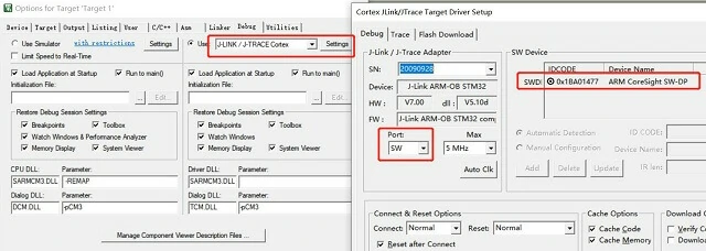
我对该芯片做过详细说明。芯片下载代码使用j-link,如下图所示:
这是j-link的简易版本,仅支持SWD调试和下载,不支持JTAG。但对于STM32芯片开发,SWD调试已足够。
将代码下载到STM32芯片
确保j-link与STM32F103ZE的连接正确,然后可在KEIL开发环境中识别出芯片:M32F103ZE的连接正确,然后可在KEIL开发环境中识别出芯片:
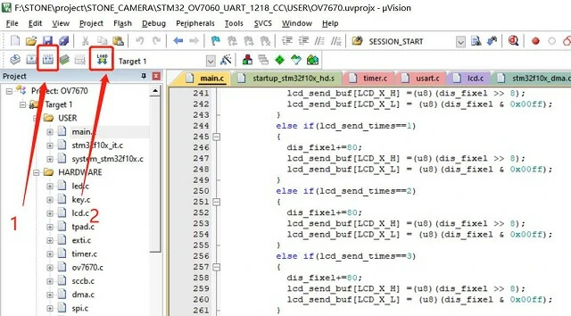
点击下载按钮将代码下载到芯片:
STM32控制代码
STONE串口屏的数据接收每次只能接收255字节,而单个RGB565数据的图像大小为240×320×2=153600字节=153.6KB,因此需要分批传输。示模块的数据接收每次只能接收255字节,而单个RGB565数据的图像大小为240×320×2=153600字节=153.6KB,因此需要分批传输。
此外,由于串行通信速率的限制,图片实时刷新效果不佳。串口波特率配置为921600,这也是STONE串行显示模块的最高通信波特率。
显示屏上的按钮和文本具有对应的地址。在本项目中,显示屏组件的地址如下:。在本项目中,显示屏组件的地址如下:
拍照按钮:0X002A
颜色和灰度按钮:0X002B
更改比例按钮:0X002C
上一张图片按钮:0X002D
下一张图片按钮:0X002E
浏览按钮:0X002F
主功能代码如下:
#include "led.h"#include "delay.h"#include "key.h"#include "sys.h"#include "lcd.h"#include "usart.h"#include "string.h"#include "ov7670.h"#include "tpad.h"#include "timer.h"#include "exti.h"#include "usmart.h"#include "dma.h"#include "sdio_sdcard.h"extern u8 ov_sta;extern u8 img_dis_cnt;extern u8 data_ready;extern u8 USART_RX_END;u16 user_width=240;u16 user_heigh=240;#define PIC_TOTAL 20u8 sd_select=1;u16 color_r;u16 color_g;u16 color_b;void UART1_Send_Array(u8 send_array[],u16 num){u16 i=0;while(i<num)< span=""></num)<>{USART_SendData(USART1,send_array[i]);while( USART_GetFlagStatus(USART1,USART_FLAG_TC)!= SET);i++;}}void ov7670_clock_set(u8 PLL){u8 temp=0;RCC->CFGR&=0XFFFFFFFC;RCC->CR&=~0x01000000;RCC->CFGR&=~(0XF<<18);PLL-=2;//µÖÏû2¸öµ¥Î»RCC->CFGR|=PLL<<18;RCC->CFGR|=1<<16; //PLLSRC ONFLASH->ACR|=0x12;RCC->CR|=0x01000000; //PLLONwhile(!(RCC->CR>>25));RCC->CFGR|=0x02;while(temp!=0x02){temp=RCC->CFGR>>2;temp&=0x03;}}#define SEND_BUF_SIZE 169#define LCD_X_H 5#define LCD_X_L 6#define LCD_Y_H 7#define LCD_Y_L 8u8 lcd_send_buf[SEND_BUF_SIZE]={0xa5,0x5a,0xa6,0x85,0x00,0x00,0x00,0x00,0x00};u8 lcd_send_buf1[512]={0x00,0x00,0x00,0x00,0x00,0x00,0x00,0x00,0x00,0x00,0x00};u8 upda_flag=1;u16 dis_fixel=0;void camera_refresh(){u16 i=0,j=0,k=0;u8 color;u8 cnt=9;u16 user_x_cnt=0,user_x_start=0,lcd_send_times=0;u16 user_width1=user_width;u16 user_heigh1=user_heigh;if(user_width1==240){user_x_cnt=2;user_x_start=450;}else if(user_width1==320){user_x_cnt=3;user_x_start=410;}else if(user_width1==160){user_x_cnt=1;user_x_start=490;}else if(user_width1==80){user_x_cnt=0;user_x_start=530;}if(ov_sta==2){OV7670_RRST=0;OV7670_RCK_L;OV7670_RCK_H;OV7670_RCK_L;OV7670_RRST=1;OV7670_RCK_H;upda_flag=0;for(i=0;i<user_heigh1;i++)< span=""></user_heigh1;i++)<>{k=i+150;lcd_send_buf[LCD_Y_L] = (u8)(k & 0x00ff);lcd_send_buf[LCD_Y_H] = (u8)(k >> 8);cnt=9;lcd_send_times=0;for(j=0;j<user_width1*2;j++)></user_width1*2;j++)>{OV7670_RCK_L;color=(u8)GPIOC->IDR&0XFF;OV7670_RCK_H;lcd_send_buf[cnt++]=color;if(cnt > 168){if(lcd_send_times==0){dis_fixel=user_x_start;lcd_send_buf[LCD_X_H] =(u8)(dis_fixel >> 8);lcd_send_buf[LCD_X_L] = (u8)(dis_fixel & 0x00ff);}else if(lcd_send_times==1){dis_fixel+=80;lcd_send_buf[LCD_X_H] =(u8)(dis_fixel >> 8);lcd_send_buf[LCD_X_L] = (u8)(dis_fixel & 0x00ff);}else if(lcd_send_times==2){dis_fixel+=80;lcd_send_buf[LCD_X_H] =(u8)(dis_fixel >> 8);lcd_send_buf[LCD_X_L] = (u8)(dis_fixel & 0x00ff);}else if(lcd_send_times==3){dis_fixel+=80;lcd_send_buf[LCD_X_H] =(u8)(dis_fixel >> 8);lcd_send_buf[LCD_X_L] = (u8)(dis_fixel & 0x00ff);}if(USART_RX_END==1){EXTI_ClearITPendingBit(EXTI_Line8);ov_sta=0;upda_flag=1;return;}else{UART1_Send_Array(lcd_send_buf,169);}lcd_send_times++;if(lcd_send_times>user_x_cnt)lcd_send_times=0;cnt=9;}}}EXTI_ClearITPendingBit(EXTI_Line8);ov_sta=0;upda_flag=1;}}void clear_display(){u16 i=0,j=0,k=0;u8 cnt=9,lcd_send_times=0;u8 color;u16 user_x_cnt=0,user_x_start=0;u16 user_width1=user_width;u16 user_heigh1=user_heigh;if(user_width1==240){user_x_cnt=2;user_x_start=450;}else if(user_width1==320){user_x_cnt=3;user_x_start=410;}else if(user_width1==160){user_x_cnt=1;user_x_start=490;}else if(user_width1==80){user_x_cnt=0;user_x_start=530;}upda_flag=0;for(i=0;i<user_heigh1;i++)< span=""></user_heigh1;i++)<>{k=i+150;lcd_send_buf[LCD_Y_L] = (u8)(k & 0x00ff);lcd_send_buf[LCD_Y_H] = (u8)(k >> 8);cnt=9;lcd_send_times=0;for(j=0;j<user_width1*2;j++)></user_width1*2;j++)>{OV7670_RCK_L;color=(u8)GPIOC->IDR&0XFF;OV7670_RCK_H;lcd_send_buf[cnt++]=0xff;if(cnt > 168){if(lcd_send_times==0){dis_fixel=user_x_start;lcd_send_buf[LCD_X_H] =(u8)(dis_fixel >> 8);lcd_send_buf[LCD_X_L] = (u8)(dis_fixel & 0x00ff);}else if(lcd_send_times==1){dis_fixel+=80;lcd_send_buf[LCD_X_H] =(u8)(dis_fixel >> 8);lcd_send_buf[LCD_X_L] = (u8)(dis_fixel & 0x00ff);}else if(lcd_send_times==2){dis_fixel+=80;lcd_send_buf[LCD_X_H] =(u8)(dis_fixel >> 8);lcd_send_buf[LCD_X_L] = (u8)(dis_fixel & 0x00ff);}else if(lcd_send_times==3){dis_fixel+=80;lcd_send_buf[LCD_X_H] =(u8)(dis_fixel >> 8);lcd_send_buf[LCD_X_L] = (u8)(dis_fixel & 0x00ff);}UART1_Send_Array(lcd_send_buf,169);lcd_send_times++;if(lcd_send_times>user_x_cnt)lcd_send_times=0;cnt=9;}}}EXTI_ClearITPendingBit(EXTI_Line8);ov_sta=0;upda_flag=1;}void user_save_image(){u16 i=0,j=0,k=0;u8 color;u8 cnt=9,m_cnt=0;u16 user_x_cnt=0,user_x_start=0,lcd_send_times=0;u16 user_width1=user_width;if(user_width1==240){user_x_cnt=2;user_x_start=450;}else{return;}while(ov_sta!=2);if(ov_sta==2){OV7670_RRST=0;OV7670_RCK_L;OV7670_RCK_H;OV7670_RCK_L;OV7670_RRST=1;OV7670_RCK_H;upda_flag=0;for(i=0;i<240;i++){k=i+150;lcd_send_buf[LCD_Y_L] = (u8)(k & 0x00ff);lcd_send_buf[LCD_Y_H] = (u8)(k >> 8);cnt=9;lcd_send_times=0;for(j=0;j<240*2;j++){OV7670_RCK_L;color=(u8)GPIOC->IDR&0XFF;OV7670_RCK_H;lcd_send_buf[cnt++]=color;if(cnt > 168){m_cnt=0;if(lcd_send_times==0){dis_fixel=user_x_start;lcd_send_buf[LCD_X_H] =(u8)(dis_fixel >> 8);lcd_send_buf[LCD_X_L] = (u8)(dis_fixel & 0x00ff);for(m_cnt=0;m_cnt<169;m_cnt++){lcd_send_buf1[m_cnt]=lcd_send_buf[m_cnt];}}else if(lcd_send_times==1){dis_fixel+=80;lcd_send_buf[LCD_X_H] =(u8)(dis_fixel >> 8);lcd_send_buf[LCD_X_L] = (u8)(dis_fixel & 0x00ff);for(m_cnt=0;m_cnt<169;m_cnt++){lcd_send_buf1[m_cnt+169]=lcd_send_buf[m_cnt];}}else if(lcd_send_times==2){dis_fixel+=80;lcd_send_buf[LCD_X_H] =(u8)(dis_fixel >> 8);lcd_send_buf[LCD_X_L] = (u8)(dis_fixel & 0x00ff);for(m_cnt=0;m_cnt<169;m_cnt++){lcd_send_buf1[m_cnt+169*2]=lcd_send_buf[m_cnt];}}UART1_Send_Array(lcd_send_buf,169);lcd_send_times++;if(lcd_send_times>user_x_cnt){SD_WriteDisk(lcd_send_buf1,i+240*sd_select,1);lcd_send_times=0;}cnt=9;}}}}EXTI_ClearITPendingBit(EXTI_Line8);ov_sta=0;upda_flag=1;}void read_image(){u8 i=0;for(i=0;i<240;i++){if(SD_ReadDisk(lcd_send_buf1,i+240*sd_select,1)==0){UART1_Send_Array(lcd_send_buf1,507);}}}int main(void){u8 pixel_ch_flag=0,user_effect_flag=0;delay_init();NVIC_Configuration();uart_init(921600);LED_Init();LCD_Init();delay_ms(1000);delay_ms(1000);while(OV7670_Init())//³õʼ»¯OV7670{delay_ms(200);}while(SD_Init()){delay_ms(500);LED0=!LED0;}if(SD_ReadDisk(lcd_send_buf1,240*(PIC_TOTAL+10),1)==0){sd_select=lcd_send_buf1[0];if(sd_select>=PIC_TOTAL ){lcd_send_buf1[0]=0x00;SD_WriteDisk(lcd_send_buf1,240*(PIC_TOTAL+10),1);sd_select=0;}}//show_sdcard_info();EXTI8_Init();OV7670_CS=0;config_ov7670_OutPut(20,60,user_width,user_heigh,0);while(1){if(USART_RX_END==1){switch(USART_RX_BUF[5]){case 0x2c:clear_display();pixel_ch_flag+=1;//!pixel_ch_flag;if(pixel_ch_flag>3)pixel_ch_flag=0;if(pixel_ch_flag==1){user_width=160;user_heigh=160;}else if(pixel_ch_flag==2){user_width=80;user_heigh=80;}else if(pixel_ch_flag==3){user_width=320;user_heigh=240;}else{user_width=240;user_heigh=240;}config_ov7670_OutPut(20,60,user_width,user_heigh,0);if(user_effect_flag)OV7670_Special_Effects(1);elseOV7670_Special_Effects(0);break;case 0x2b:user_effect_flag=!user_effect_flag;if(user_effect_flag)OV7670_Special_Effects(1);elseOV7670_Special_Effects(0);break;case 0x2a:if(user_width!=240)break;if(img_dis_cnt==0){img_dis_cnt=1;}else{if(SD_ReadDisk(lcd_send_buf1,240*(PIC_TOTAL+10),1)==0){if(lcd_send_buf1[0]>=PIC_TOTAL){lcd_send_buf1[0]=PIC_TOTAL;sd_select=1;}else{sd_select=lcd_send_buf1[0]+1;lcd_send_buf1[0]=sd_select;}SD_WriteDisk(lcd_send_buf1,240*(PIC_TOTAL+10),1);user_save_image();//sd_select=lcd_send_buf1[0];}}break;case 0x2d:if(SD_ReadDisk(lcd_send_buf1,240*(PIC_TOTAL+10),1)==0){if(lcd_send_buf1[0]==0)break;else{sd_select-=1;if(sd_select==0)sd_select=lcd_send_buf1[0];}if(sd_select>lcd_send_buf1[0])sd_select=1;}if(user_width==320)clear_display();read_image();img_dis_cnt=0;break;case 0x2e:if(SD_ReadDisk(lcd_send_buf1,240*(PIC_TOTAL+10),1)==0){if(lcd_send_buf1[0]==0)break;if(sd_select>=lcd_send_buf1[0]){sd_select=1;}else{sd_select+=1;}}if(user_width==320)clear_display();read_image();img_dis_cnt=0;break;case 0x2f:img_dis_cnt=0;break;default:break;}USART_RX_END=0;USART_RX_STA=0;}else{// USART_RX_END=0;// USART_RX_STA=0;if(img_dis_cnt==1)camera_refresh();}}}}
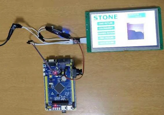
最后,将代码下载到STM32芯片,然后将完成的电路板连接到显示屏,并确保电源稳定。您可以通过STONE串口屏查看VO7670拍摄的图片。
OV7670摄像头模块与STONE串口屏连接,项目结束。
运行效果