Nordic51822 brief introduction
NRF51822 is a 2.4g multi-protocol SoC with powerful functions and high flexibility, which is very suitable for Bluetooth low-power and 2.4ghz ultra-low-power wireless applications.NRF51822 is built based on the 32-bit arm cortex-m kernel, with 256kB flash + 16kB RAM. Embedded 2.4ghz transceiver supports Bluetooth low power consumption and 2.4ghz operation, in which 2.4ghz mode is compatible with nRF24L series products of Nordic Semiconductor.
NRF51822’s 31 GPIO mapping schemes enable I/O (such as serial interface, PWM, and sine demodulator) to be mapped to any device pin as indicated by PCB requirements. This allows for complete design flexibility and pin position and function.
NRF51822 supports the S110 Bluetooth low-power protocol stack and the 2.4ghz protocol stack (including Gazell), both of which are free of charge in the software development suite of nRF51822.
NRF51822 needs a separate power supply. If the power supply range is between 1.8-3.6v, the user can choose to use the linear rectifier on the chip. If the power supply range is between 2.1-3.6v, the user can choose the dc 1.8v mode and the DCDC transformer on the chip. The use of the dc-dc transformer can be dynamically controlled during operation and the peak rf current of nRF51822 during operation is less than 10 mA (3V, tx@0 dBm & RX).
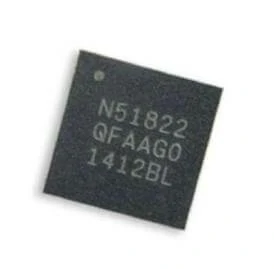
NRF51822 has a 6x6mmQFN48 package and a 3.5×3.8mm package (WLCSP).
NRF51822 offers 256k or 128kB Flash capacity in different versions.
About NRF51822 Power consumption
- 6.3mA – TX at -4dBm (3V using on-chip DC-DC)
- 8.0mA – TX at 0dBm (3V using on-chip DC-DC)
- 11.8mA – TX at +4dBm (3V using on-chip DC-DC)
- 9.7mA – RX (3V using on-chip DC-DC)
- 13mA – RX at 1Mbps (No DC-DC)
- 10.5mA – TX at 0dBm (No DC-DC)
- 0.6µA – SYSTEM-OFF, no RAM retention
- 1.2µA – SYSTEM-OFF, 8KB RAM retention
- 2.6µA – SYSTEM-ON, All peripherals in idle mode
Reception sensitivity
- +4dBm to -20dBm output power in 4dBm steps
- -30dBm output power in whisper mode
- -96dBm RX sensitivity at 250kbs
- -90dBm RX sensitivity at 1Mbps
- -85dBm RX sensitivity at 2Mbps
- 2 Mbps, 1 Mbps, and 250kbs supported data rates
- Excellent co-existence performance
peripherals
- 3 x 16/24-bit timer with counter mode
- 16 – channel programmable peripheral product interconnection (PPI) system
- Encryption -128-bit AES ECB/CCM/AAR coprocessor
- Random number generator (RNG)
- Real-time clock (RTC)
- Temperature sensor
- GPIO pin configuration that can be mapped at will
- 31 GPIO available
- 4 road PWM
- SPI- master/slave, IIC, UART
- 8/9/10 bit ADC – 8 configurable channels
Application
Bluetooth watch, bracelet, wearable smart devices
Bluetooth scale
Smart home
Bluetooth anti-loss device
An introduction to 51822 Nordic51822 Development board
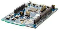
NRF51822 hardware development tools include a development board and USB DONGLE.NRF51 DK and nRF51DONGLE include nRF51822 and nRF51422 SoCs, supporting the development of Bluetooth Smart, ANT, and 2.4ghz proprietary technologies.
nRF51 DK
NRF51 DK is a multifunctional veneer development kit that supports programming and debugging via Jlink (Segger OB) and Mbed.
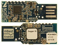
nRF51 Dongle
NRF51 Dongle is a small USB interface with the same program and debugging functions as nRF51 DK. Its main purpose is to interact with pc-based development tools and Nordic utilities so that it can be used as a prototype device for monitoring air traffic, or as a subminiature development board.
NRF51822 Software development
The software is divided into two main parts:
- Wireless protocol stack;
- SDK can be downloaded from the official website: https://www.nordicsemi.com/chi_simple
Tools
Nordic provides a series of tools that enable users to interact and monitor with prototypes/products:
| TOOL | introduce |
| nRFgo Studio | PC tools allow programming and radio performance testing on nRF51 devices |
| Master Control Panel | A peer-to-peer device simulator that allows you to connect directly to and interact with Bluetooth services in the product. This is a great tool to check that your product identifies itself and its capabilities in the right way, and to test how it responds to correct and incorrect actions in your peer.
MCP is a Windows PC application (using nrf51-dongle). |
| nRF Master Control Panel | A powerful universal tool that lets you scan and explore your Bluetooth smart devices and communicate with them. NRF MCP is an application on Android. |
| ANTware | A peer-to-peer device emulator for the ANT protocol running on a PC, which runs with nrf51-dongle.This is a great tool to check if your product recognizes itself and its capabilities, and how it responds to correct and incorrect actions in your peer. |
| nRF Sniffer | If communication with the three Bluetooth smart ready peers does not work as expected, the nRF Sniffer enables you to monitor all air communications between you and your peers through link establishment, security negotiation. |
| nRF51-BLE-Driver | Windows DLL that connects the MCP to the nRF51 adapter. Provides an API similar to our software appliance for PC applications, making it an ideal choice for your own pc-based testing and presentation tools. |
| nRFjprog (part of nRF51 toolset installer) | Command-line utility, through Jlink programmer/debugger support nRF51 device programming. |
| Mergehex (part of nRF51 toolset installer) | Since the Nordic software is precompiled with hex files, at least two hex files will be generated when you add your own application, and mergehex is a command-line utility that merges multiple hex files into one. |
| JlinkARM (part of nRF51 toolset installer) | Jlink debugger driver |
You can find the tools on the official website.
5 tools for Software development preparation
So many tools have been introduced, but in the early stage of development, we only need to prepare the following software and tools:
- Development board
- The SDK
- The NRF GO STUDIO
- KEIL MDK
- J – Link
Then install the NRF GO STUDIO.
When the development board first downloaded the program, it needed to use the NRF GO protocol stack (wipe flash before burning).
Then KEIL MDK is used to open the routines in the SDK, and after compiling, click load to download the program to the internal FLASH chip.
Note: the Nordic SDK and the protocol stack are separate, and the versions of the protocol stack and the SDK can only be used in accordance with each other. When you download the protocol stack into the internal FLASH of the chip for the first time, if you use a different version of SDK next time, you need to erase the protocol stack with NRF GO STUDIO before using it.
BLE to UART-TTL Test
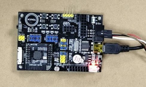
Connect the development board to the computer:
Then open the installed NRFGO STUDIO software and erase FLASH first:
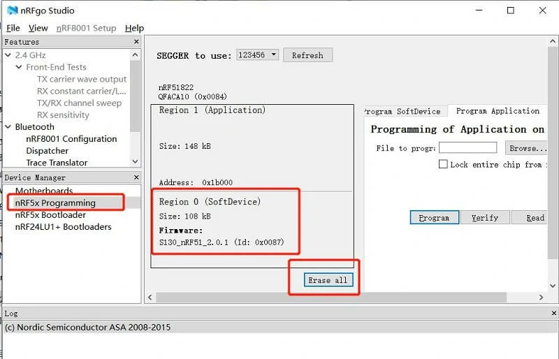
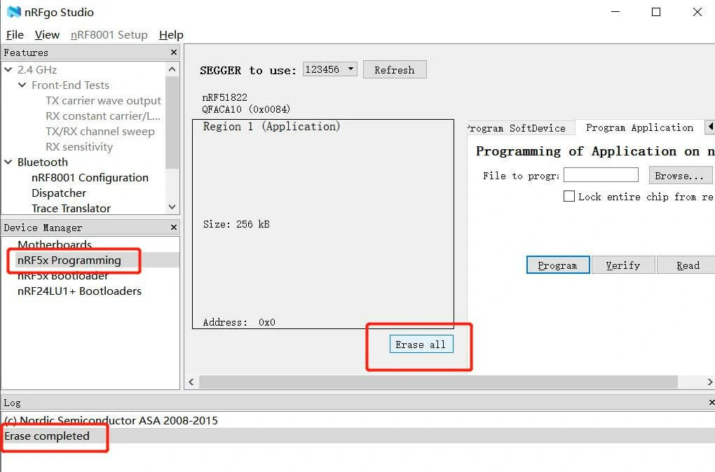
The successful erasure will be prompted in the status bar below.
Then select “Program SoftDevice” and burn protocol stack. The protocol stack is in the SDK directory:
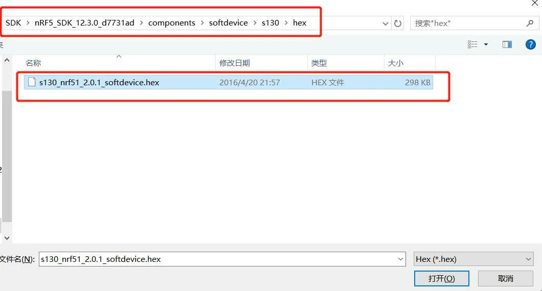
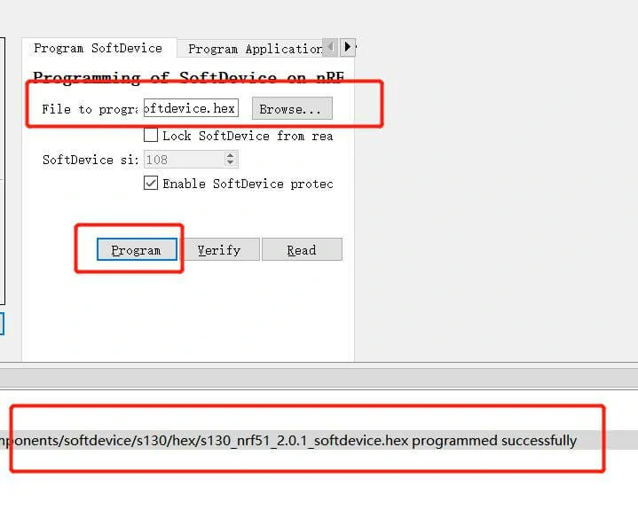
Once you’ve done this, you can open the BLE-UART Demo in the SDK.
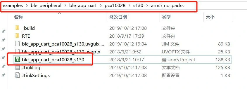
The first time you open it, you will be prompted to install PACK. Just follow the prompts. If KEIL’s automatic download speed is too slow, you can search the relevant PACK on the Internet and download and install it directly.
After the code is opened, it is compiled and then burned through the KEIL development environment
FLASH of NRF51822 chip:
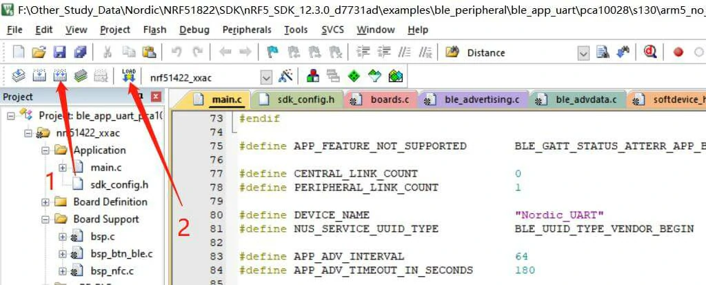
Then reset the development board and you can search for the Bluetooth name with your phone. The name for Bluetooth is Nordic UART
Data transceiver test
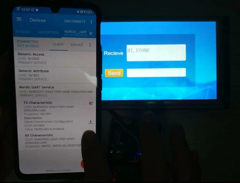
NRF Connect is recommended for android phones, and LightBlue is recommended for IOS users in the APP Store. Here is an example of NRF Connect:
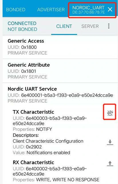
Open the NRF Connect software, search the name of Bluetooth Nordic UART, and then click the Connect button to Connect the 51822 Bluetooth chip.
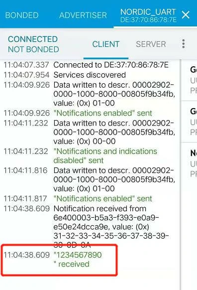
Send data in the serial assistant and the mobile APP will receive the data:
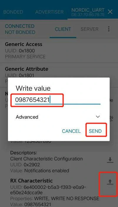
The serial assistant can also receive the data sent by the mobile phone by sending data in the mobile phone APP:
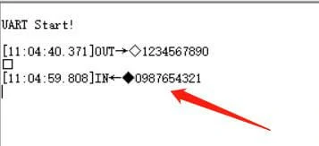
After this step, the data sending and receiving test of the Bluetooth chip was completed. However, in the actual project, it was impossible to send and receive data through the serial port assistant software, so I needed a more intuitive user interface.
7 inch HMI display STONE TFT-LCD module
The STONE 7 inch HMI display TFT-LCD display module can communicate with the MUC through UART(RS232/TTL), and the MCU can send instructions to the LCD screen to display user data.
The display is simple to use and comes in a variety of models (industrial and civilian).
800*480 STONE STVC070WT-01
I use the display screen of the model STVC070WT-01, which can communicate directly with the MCU through UART-TTL. In this experiment, the Nordic51822 chip was able to control the display content directly through the UART.
The working process of the STONE TFT-LCD display module
The intelligent TFT-LCD module communicates with the customer’s MCU (hexadecimal code) through UART-TTL, and the MCU will then control the connected device according to the command received.
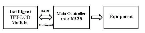
Using the STONE TFT-LCD display module only requires 3 steps:
- Design a beautiful set of graphical user interfaces.
- Directly connect to MCU through UART-TTL.
- Write a simple program to control the TFT-LCD module by MCU command. (hexadecimal code).
TFT LCD module serial command frame consists of 5 data blocks, all serial commands or data are expressed in hexadecimal format. The data transfer
In the MSB way.For example, for 0x1234, first send 0x12, then 0x34.
A UI graphic interface design for STONE TFT-LCD
I need to design a UI picture. I use photoshop. After the design, I save it as a JPG format.

After designing the picture, we need to use the TOOL software provided by the official website of STONE to add components. About the use and download of the TOOL software, you can find it on the official website: https://www.stone-hmi.com//
Using STONE TOOL2019 to add 3 component
Add the designed UI picture to the new project of STONE TOOL software, and then add font library and keyboard picture:
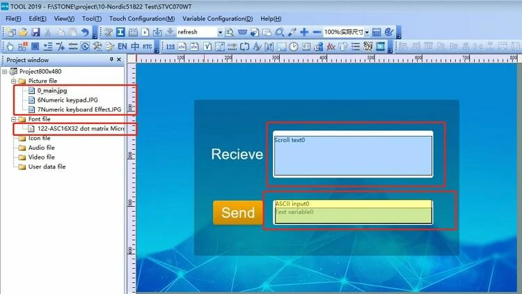
After completion, you can click the button in the toolbar to generate the configuration file, and then download the configuration file into the STONE STVC070WT-01-01 display, and it will display normally.
The simulation effect of STONE TOOL software is as follows:
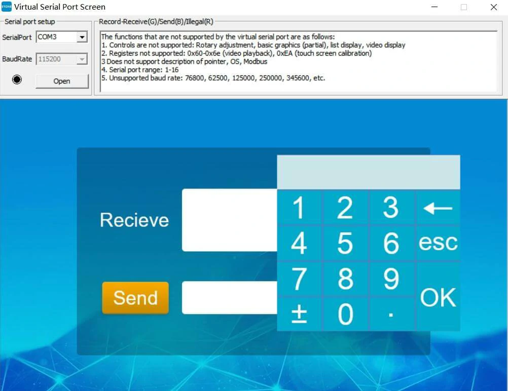
The numeric keypad is pop-up, meaning it pops up only when the user clicks on the appropriate area.
Download the configuration file to STONE STVC070WT-01 display
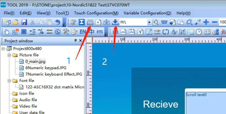
The computer first inserts the U disk, according to the steps marked in the picture, you can first download the configuration file into the U disk, then unplug the U disk, insert the U disk into the STONE STVC070WT-01, then you can automatically upgrade the configuration file of the display screen.
NRF51822 and STONE LCD screen connection with uart-ttl
According to the code of NRF51822, we can see the configuration of the UART pin:

All you need to do is connect these two pins to the RX and TX of the STONE display, and connect GND.
In the process of the actual test, the Nordic website provides the BLE – UART code is a bit of a problem, more than 20 bytes is when a data transceiver, the chip will be reset to restart, this is because the default MTU length 23 bytes, only need to do some modify of MTU, specific modification method in this I will not be introduced, interested friends can go to the Internet to find information.
Modify the code to communicate with STONE LCD via UART-TTL
In order for the 51822 and STONE displays to communicate, the handshake protocol needs to be modified.
Modify UART receive end conditions
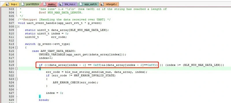
Originally, “\n” was the end condition of receiving, while the STONE display was sending the end byte with two 0xff as the number, so it was changed to the code on the way.
Bluetooth send data package for STONE LCD
There are format requirements for the data received by the STONE display screen. It only needs to add 6 more bytes to the data sent to the display screen:
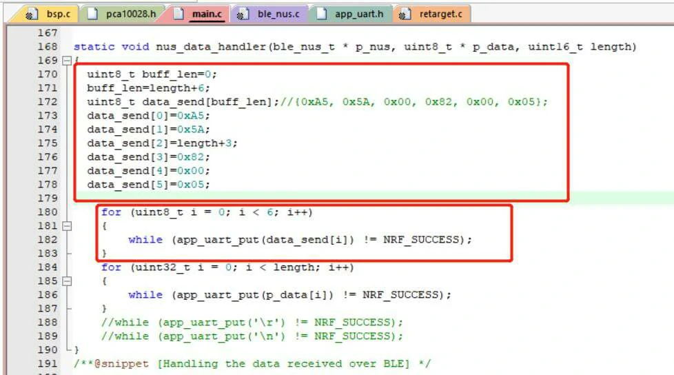
NRF51822 and STONE LCD screen working test