四种主要仪表故障的原因及解决方法
为了实现工业串口屏控制生产,必须对生产过程中温度、压力、流量、液位等数据进行全面监测。这些功能通过相应的检测仪表实现。一旦仪表发生故障,将对工业生产正常运行造成严重影响。
因此,工业控制人员必须熟悉四种仪表的物理结构、测量原理和性能指标,能够准确诊断并处理仪表故障,以确保工业生产正常进行。
工业串口屏控制系统中的四大主要仪表是什么?
1 温度计
石油化工生产中的化学反应和变化需要在特定的温度和压力环境下顺利进行。为了实时监测温度变化并精确控制温度范围,生产过程中必须设置一定数量的温度计。目前,生产温度主要通过接触方式测量,温度数据由热电偶、热电阻等温度测量元件采集,并借助现场总线技术实现自动温度控制。
热电偶与热电阻的识别
工业用热电偶和热电阻保护套的外观几乎相同,部分温度测量元件体积非常小,如铠装型,其外观也基本一致。
A.在铭牌上,通过型号即可识别。
热电偶:原理为热电效应,其分级符号为S、B、E、K、 R、J、T七种标准化型号。
热电阻:原理是电阻的热效应(导线或半导体的电阻值随温度变化的特性),其等级符号为Pt10、Pt100、Pt1000、Cu50和Cu100。PT100和CU50是最常用的。
B.在无铭牌且未知型号的情况下,可采用以下方法进行识别。
(1) 观察温度测量元件的引线,通常热电偶仅有两根引线,若有三根引线则为热电阻。
然而,对于四根引线的元件,需测量电阻值以确定是两支热电偶还是四线热电阻。首先,从四根引线中找到两对电阻值接近零的引线,然后测量这两根引线之间的电阻值。若电阻值为无穷大,则为双热电偶。一对电阻值接近零的导线为热电偶。若两对导线电阻值在10-110之间,则为单四线热电阻,其电阻值最接近哪个指数的热电阻值,该指数即为该热电阻的指数值。
(2) 若仅有两根引线,可使用数字万用表测量电阻值进行判断,因热电偶的电阻值极小,热电阻几乎为零;若电阻值极小,可能是热电偶。热电阻在室温下的最小电阻值将大于10。
2 压力表
压力表种类繁多,如压力传感器、压力变送器、专用压力表等。压力表可用于高温、腐蚀等极端环境下的压力测量,也可用于易结晶和粉粒状介质的压力测量。
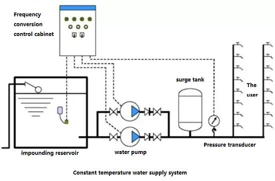
在正常情况下,压力调节系统会通过压力变送器将采集的信号传输至分布式控制系统,以实现自动压力测量和控制效果。
- 液位仪表
根据不同的测量方法,液位仪表可分为浮球式、直接读数式、差压式、辐射式、雷达式等。在石油化工生产中,由于其测量精度高且对石油化工材料适应性强,雷达液位仪表逐渐受到行业的青睐。
4 流量计
流量计基本基于两种测量原理:一种是体积流量测量,另一种是质量流量测量。孔板差压流量计、电磁流量计、超声波流量计、涡街流量计等,目前几乎所有流量计均为体积检测流量计。由于当前应用智能化,只要改变流量计内部参数,也可检测质量流量。
仪表故障原因分析
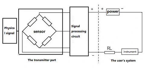
通常,自动控制仪表由三部分组成:传感器、变送器和显示器。传感器负责检测被测对象的模拟信号。变送器负责将传感器输出信号转换为标准电流信号(4~20 mA),并传输至PLC控制器;显示器负责显示测量数据。
仪表故障通常表现为异常指示,如低指示、高指示、指示不稳、异常波动等,其原因可归纳为两类:
- 被测参数本身异常;
- 测量系统某一环节发生故障,导致数据显示不准确。
要正确诊断故障原因:
- 具备仪表测量原理、物理结构及工作特性的基本了解;
- 熟悉测量系统整个工作流程;
- 深入了解工业生产工艺、物料特性、设备性能等。
以下对仪表常见的四种故障进行具体说明。
- 流量计故障
1) 若流量计读数达到最高值,现场测试仪表也会显示最高值,此时手动调节远程调节阀的开度,若流量值下降,则为工艺问题;若流量值不变,则为仪表系统故障。需检测仪表信号传输系统及压力引线系统是否异常。
2) 若流量指数异常波动,可将系统从自动控制切换至手动控制。若波动仍存在,则为工艺原因;若波动减小,则表明PID参数或仪表存在问题。
3) 若仪表流量降至最低,首先检查现场仪表,若现场仪表也显示最低值,检查调节阀的开度,若开度为零,则故障发生在流量调节装置;若开度正常,则很可能是物料结晶、管道堵塞或压力过低所致。若现场仪表正常,指示异常则表明仪表存在问题,原因通常为机械仪表齿轮卡滞、差压变送器正压腔泄漏等。
- 液位仪表故障
1) 当液位仪表值达到最高或最低时,应根据现场测试仪表进行判断。若现场仪表正常,应将系统切换至手动控制以检查液位是否变化。若液位能在一定范围内保持稳定,表明液位控制系统存在问题;否则,系工艺原因所致。
2) 对于差压液位仪表,当控制仪表显示数据与现场测试仪表不一致,且现场仪表无明显异常时,检查压力导管的液体密封是否正常。若存在泄漏,添加密封液体,仪表归零;若无泄漏,初步判断仪表负迁移错误,需进行校正。
3) 当液位控制仪表数据异常波动时,应根据设备容量进行判断。若设备容量较大,通常为仪表故障;若设备容量较小,需先检查工艺操作。若工艺操作发生变化,最可能是工艺原因导致的波动,否则为仪表问题。
- 压力表故障
当压力仪表数据异常时,应根据被测介质的物理状态(固态、液态或气态)进行针对性检测与诊断。
1) 当压力控制仪表出现异常波动时,需首先确认工艺操作是否发生变化,因这类变化多由工艺操作异常或PID参数设置不当引起。
2) 当控制仪表出现滞后现象,即工艺操作发生变化但仪表数据保持不变时,通常是压力测量系统故障。此时应首先确认压力导管是否堵塞。若管道畅通,则确认压力变送器输出装置是否处于正常状态。若发现异常变化,可确认问题出在测量显示系统。
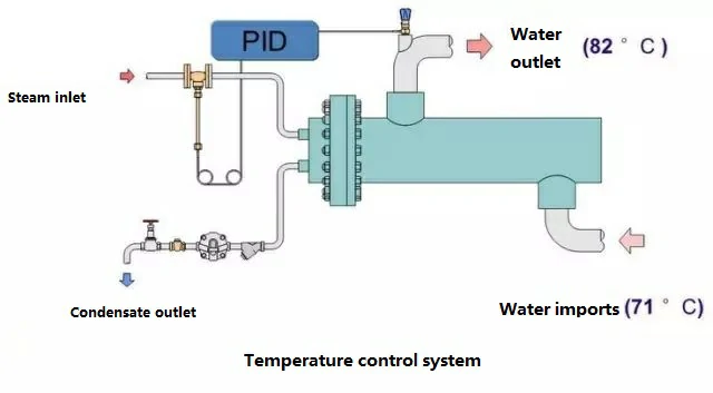
- 温度仪表故障
温度仪表故障通常表现为高、低或响应缓慢。当温度仪表发生故障时,应注意以下两点:首先,温度仪表大多为电气仪表;其次,在仪表测试时系统存在明显的滞后现象。
1) 温度仪表数据突然变化至最高或最低水平,通常属于仪表系统问题。这是因为仪表系统本身存在一定滞后,突变情况罕见。若出现突变,一般由热阻、热电偶或变送器放大器异常引起。
2) 温度控制仪表出现高频异常波动,通常由PID参数设置不当引起。
3) 当温度控制仪表出现明显缓慢波动时,通常是工艺操作变化所致。若排除工艺操作影响,则最可能是仪表控制系统故障。
结论
工业串口屏仪表控制系统的应用为工业控制行业带来了极大便利,并重新定义了人类与工业控制系统之间的交互关系。
在分析和处理实际工业控制仪表故障时,不仅需要掌握扎实的仪表理论和知识,还需对工艺实践有详细了解,以便快速诊断仪表故障,并采取适当措施处理故障,确保工业生产顺利进行。