本教程在连接STWI101WT-01 串口屏与 Arduino 开发板 LY-F2 后,将重点介绍增强型控制视图, tab_view、popup、dialog、slide_view_view、list_view 等增强型控件。熟悉这些增强型控件后,您将能够通过 STONE 串口屏实现更丰富、多维度且灵活的界面设计,使产品的人机交互更加人性化、美观且酷炫!
目录。
- 将 Arduino 与 STONE 串口屏连接。
- 弹出窗口
- 对话框
- 视图
- Tab_view
- Slide_view_view
- List_view
- 界面编程与代码
1、将Arduino连接到STONE 串口屏。
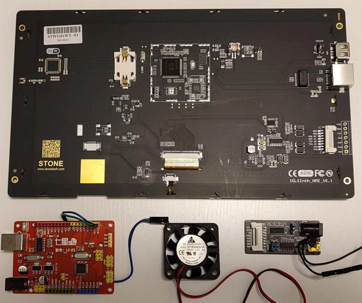
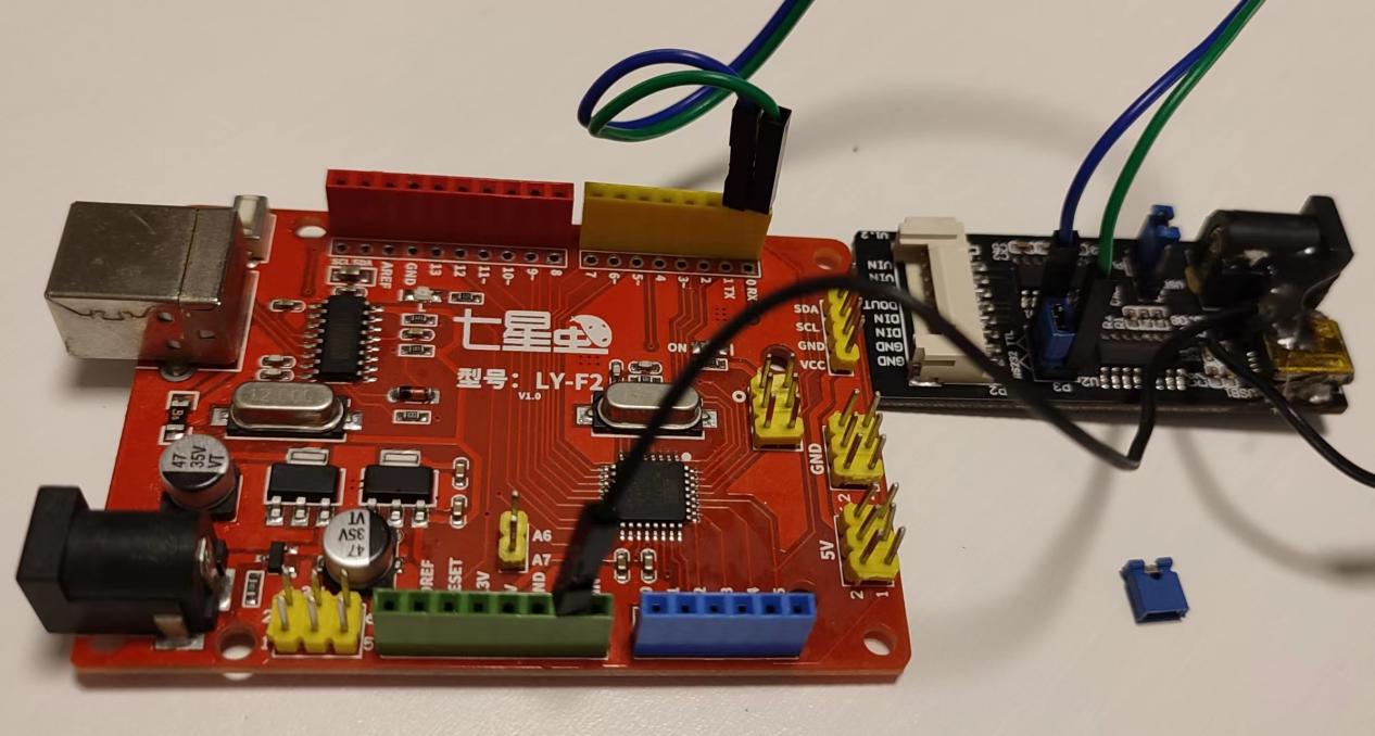
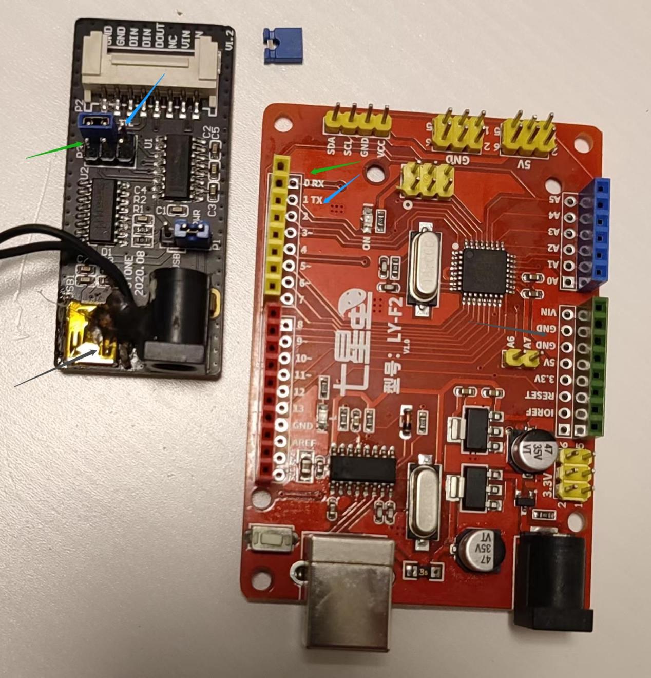
如图(11)所示,顶部为STONE的STWI101WT-01串口屏,红色部分为Arduino开发板LY-F2,风扇右侧为STONE的适配器板V1.2. 开发板 LY-F2 与 STWI101WT-01 屏幕通过串行通信连接,经由适配器板 V1.2 实现。因此,如何将适配器板 V1.2 与 Arduino 开发板 LY-F2 连接?请参见图 (12),两者需连接 3 根导线,分别对应 TX、RX、 GND,需要移动电路板上的导线,因为适配器板V1.2上没有GND引脚,如图(13)中绿色、蓝色、黑色标记所示。适配器板V1.2的DC12V也需连接,以确保串口屏幕点亮。显示屏两侧的GND与V1.2转换板上的GND需对应连接。
2. 弹出窗口介绍。
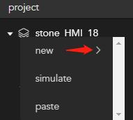
在石块设计师中右键点击项目顶层根节点,弹出右键菜单(如图 (21) 所示),然后在“新建”菜单的下方选择“弹出窗口”以生成弹出窗口。我们在弹出窗口中创建一个按钮,以实现点击后返回主页的功能。
设置弹出窗口的背景图片(bg_image)和背景颜色(bg_color),效果如图(22)所示。目前弹出窗口不支持文本属性。

3. 对话框简介。
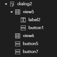
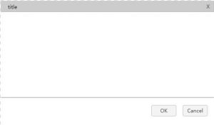
与上述操作相同,在石块设计器中右键点击项目顶层根节点,在弹出右键菜单中选择“对话框”生成对话框,项目文件会自动生成如图 (31) 所示, 窗口效果如图 (32) 所示。修改上述视图的子控件标签以显示对话框标题;修改子控件按钮,使其在点击时执行 close_window 功能以实现退出等操作。参考上述对话框对话框的 bg_image 和 bg_color 设置,效果如图 (33) 所示。

4. 视图控件简介。
我最喜欢的部分:基础控件 radio_button 可以通过视图 tab_view 进行分组。这个问题困扰了我很久,哈哈……
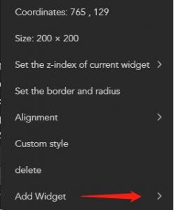
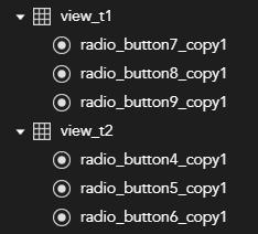
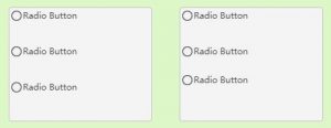
当你创建一个视图控件时,可以在石块设计器的左侧项目列中选中它,然后右键点击以打开右键菜单 (41),将光标移动到“添加控件”底部,可在展开的子菜单中选择 radio_button 控件。该按钮控件将成为视图控件的子控件,后续移动视图时,子控件会随其移动。重复上述操作可添加多个 radio_button, 并注意修改 radio_button 的 x 和 y 坐标,确保其位置正确。2 个视图控件,每个包含 3 个 radio_button,将呈现如图 (42) 所示。视图的边框颜色可设置为红色以显示边框。
5. Tab_View 控件介绍。
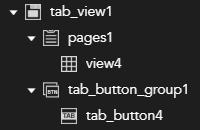
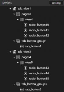
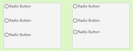
当你拖动并创建一个 tab_view 控件时,石块设计工具的左侧项目栏会自动生成,如图 (51) 所示。此时,你可以参考视图控制器,在页面下的视图中添加 radio_button 控件。图 (52) 展示了两个 tab_view 控件,分别添加了三个 radio_button 控件。视图和 tab_view 页面生成后,如图 (53) 所示。。根据需要修改 tab_button 子控件的文本属性… 效果很好!
6. slide_view_view 控件介绍。
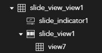
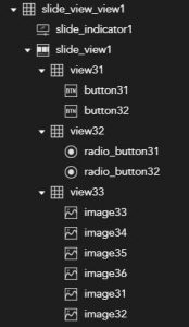
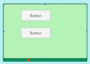
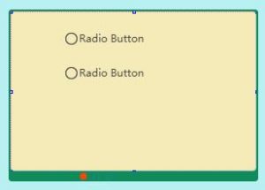
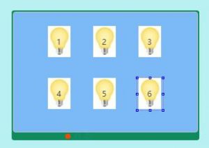
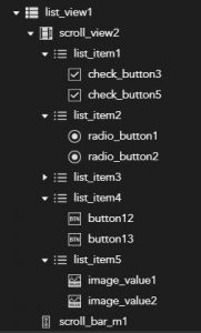
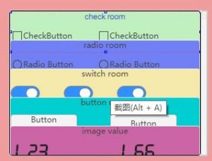
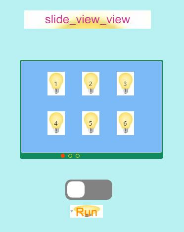
当你拖动并创建一个 slide_view_view 控件时,石块设计工具的左侧项目栏会自动生成,如图 (61) 所示。在 slide_view1 下,你可以添加多个子视图,每个视图下又可以添加多个子控件。图 (62) 中展示的三种视图效果分别对应图 (63)、图 (64) 和图 (65)。视图中子控件的 x 和 y 坐标相对于视图的左上角。
7、列表视图控件简介。
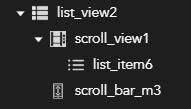
当你拖动并创建一个 list_view 控件时,石块设计工具左侧的项目栏会自动生成。如图 (71) 所示,在 scroll_view1 下,你可以添加多个子 list_item,而在每个 list_item 下,你可以添加多个其他基础子控件。这里的 list_item 通常作为 list_view 的子控件使用,不单独使用。图 (72) 的效果如图 (73) 所示,其中每个 list_item 的 bg_color 设置为不同颜色以便区分。滚动条 Scroll_bar_m3 的默认宽度为 10,可调整,且 scroll_bar_m3 的 fg_color 可设置。
8、界面编程与代码。
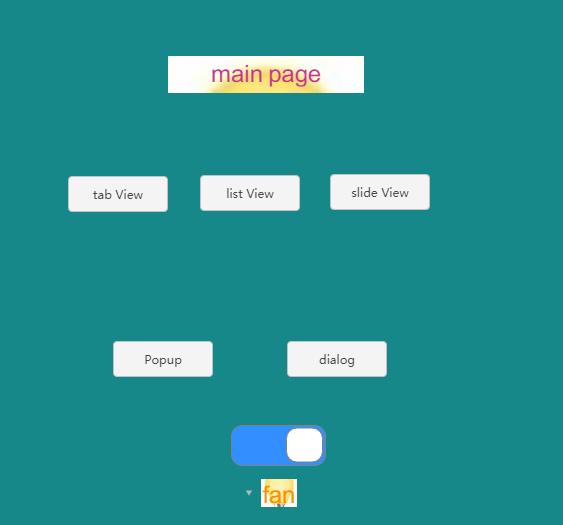
主页面如图 (81) 所示,从中可以访问各个演示页面并控制风扇的开关。风扇控制的开关控件名称为 sw1,图 (82) 中风扇控制的开关控件名称为 sw2,图 (65) 中六个灯泡图像控件的名称分别为:image31、image32、image33、image34、image35、image36。
这可以通过以下命令实现。
ST<{“cmd_code”: “set_visible”, “type”: “widget”, “widget”: “image31”, “visible”:true}>ET
# Make the visible state of the image control true.
ST<{“cmd_code”: “set_visible”, “type”: “widget”, “widget”: “image31”, “visible”:false}>ET
# 将图像控件的可见状态设置为false。
当开关sw1处于开启状态时,显示屏恢复正常。
S T < 0x10 0x10 0x00 0x04 sw1 0x01 > E T
十六进制数据:
53 54 3C 10 10 00 04 73 77 31 01 3E 45 54 AB 54
当开关 sw1 关闭时,显示恢复。
S T < 0x10 0x10 0x00 0x04 sw1 0x00 > E T
十六进制数据:
53 54 3C 10 10 00 04 73 77 31 00 3E 45 54 57 55
图 (73) 中 list_item3 中的子控件开关具有相同的返回效果!
演示说明
LY-F2 开发板通过串口转换板 V1.2 与 STWI101WT-01 显示屏通信,实现开发板与显示屏之间的交互。主页上的切换延迟控制 Arduino 板上 IO6 引脚连接的风扇的启动/停止,而滑动视图页面上的开关控制视图 33 中六个子控件图像的动画启动/停止,请参见图 (82) 和配套演示视频。
转换板 V1.2 需要 DC12V 直流电源,一个 USB 双电源供电,以及一个 USB 电源为 232 芯片提供 DC5V,否则串行通信将异常!
代码列表
开发板 Arduino 源代码如下所示。
// widget view \ tab view \ slide view \ list view \ popup \ dialog
// by Frank for STONE in 2022.06.03
/*
fan with switch control name = sw1.
switch control Run with name = sw2.
The names of the 6 bulb image controls are: image31, image32, image33, image34, image35, image36.
the word of CMD:
ST<{"cmd_code": "set_visible", "type": "widget", "widget": "image31", "visible":true}>ET
When switch switch sw1 is on, the display returns.
S T < 0x10 0x10 0x00 0x04 sw1 0x01 > E T
Hexadecimal data :
53 54 3C 10 10 00 04 73 77 31 01 3E 45 54 AB 54
When switch switch sw1 is off, the display returns.
S T < 0x10 0x10 0x00 0x04 sw1 0x00 > E T
Hexadecimal data :
53 54 3C 10 10 00 04 73 77 31 00 3E 45 54 57 55
*/
// Pin 13 has an LED connected on most Arduino boards.
// give it a name:
int led = 13;
int fan = 6;
int flagFan = 0; // Fan : 0 = stop 1 = play
int flagRun = 0;
int runNum = 1;
int iflag0 = 1;
int num3 = 0;
void setup()
{
pinMode(led, OUTPUT); // initialize the digital pin as an output.
pinMode(fan, OUTPUT);
digitalWrite(led, LOW);
digitalWrite(fan, LOW);
flagFan = 0;
Serial.begin(115200); // Open the serial communication function and wait for the serial port to open
while (!Serial) {
Needed for Leonardo only
}
}
void loop()
{
int inChar;
if(iflag0 == 1){ //only once!
iflag0 = 0;
//-------set all lamps on!------
Serial.println("ST<{\"cmd_code\":\"set_visible\",\"type\":\"widget\",\"widget\":\"image31\",\"visible\":true}>ET");
Serial.println("ST<{\"cmd_code\":\"set_visible\",\"type\":\"widget\",\"widget\":\"image32\",\"visible\":true}>ET");
Serial.println("ST<{\"cmd_code\":\"set_visible\",\"type\":\"widget\",\"widget\":\"image33\",\"visible\":true}>ET");
Serial.println("ST<{\"cmd_code\":\"set_visible\",\"type\":\"widget\",\"widget\":\"image34\",\"visible\":true}>ET");
Serial.println("ST<{\"cmd_code\":\"set_visible\",\"type\":\"widget\",\"widget\":\"image35\",\"visible\":true}>ET");
Serial.println("ST<{\"cmd_code\":\"set_visible\",\"type\":\"widget\",\"widget\":\"image36\",\"visible\":true}>ET");
delay (2000);
digitalWrite(fan, HIGH);
digitalWrite(led, HIGH);
delay (2000);
delay (2000);
digitalWrite(fan, LOW);
} //end if iflag0 = 1
//------- flagRun = 1 -------------
if(flagRun == 1)
{
if(runNum == 1) {
Serial.println("ST<{\"cmd_code\":\"set_visible\",\"type\":\"widget\",\"widget\":\"image31\",\"visible\":false}>ET");
}
if(runNum == 2) {
Serial.println("ST<{\"cmd_code\":\"set_visible\",\"type\":\"widget\",\"widget\":\"image32\",\"visible\":false}>ET");
}
if(runNum == 3) {
Serial.println("ST<{\"cmd_code\":\"set_visible\",\"type\":\"widget\",\"widget\":\"image33\",\"visible\":false}>ET");
}
if(runNum == 4) {
Serial.println("ST<{\"cmd_code\":\"set_visible\",\"type\":\"widget\",\"widget\":\"image34\",\"visible\":false}>ET");
}
if(runNum == 5) {
Serial.println("ST<{\"cmd_code\":\"set_visible\",\"type\":\"widget\",\"widget\":\"image35\",\"visible\":false}>ET");
}
if(runNum == 6) {
Serial.println("ST<{\"cmd_code\":\"set_visible\",\"type\":\"widget\",\"widget\":\"image36\",\"visible\":false}>ET");
}
if(runNum == 7) {
runNum = 0;
Serial.println("ST<{\"cmd_code\":\"set_visible\",\"type\":\"widget\",\"widget\":\"image31\",\"visible\":true}>ET");
Serial.println("ST<{\"cmd_code\":\"set_visible\",\"type\":\"widget\",\"widget\":\"image32\",\"visible\":true}>ET");
Serial.println("ST<{\"cmd_code\":\"set_visible\",\"type\":\"widget\",\"widget\":\"image33\",\"visible\":true}>ET");
Serial.println("ST<{\"cmd_code\":\"set_visible\",\"type\":\"widget\",\"widget\":\"image34\",\"visible\":true}>ET");
Serial.println("ST<{\"cmd_code\":\"set_visible\",\"type\":\"widget\",\"widget\":\"image35\",\"visible\":true}>ET");
Serial.println("ST<{\"cmd_code\":\"set_visible\",\"type\":\"widget\",\"widget\":\"image36\",\"visible\":true}>ET");
}
delay(10); // waits 1s
num3 += 1;
if(num3 >= 30){
runNum += 1;
num3 = 0;
}
}
// Read the information sent by the serial port:
if (Serial.available() > 0) { inChar = Serial.read(); }
//-------CMD jie ma begin-------
if (inChar == 0x73) // s
{
if (Serial.available() > 0){inChar = Serial.read();}
if (inChar == 0x77) // sw
{
if (Serial.available() > 0){ inChar = Serial.read();}
if (inChar == 0x31) // sw1
{
if (Serial.available() > 0){ inChar = Serial.read();}
if (inChar == 0x01) // sw1 = 1
{
if(flagFan == 0){
delay (2000);
digitalWrite(fan, HIGH);
flagFan = 1;
}
}else if (inChar == 0x00) // sw1 = 0
{
if(flagFan == 1){
delay (2000);
digitalWrite(fan, LOW);
flagFan = 0;
}
}
}else if (inChar == 0x32) // sw2
{
if (Serial.available() > 0){ inChar = Serial.read();}
if (inChar == 0x01) // sw2 = 1
{
flagRun = 1;
runNum = 1;
}else if (inChar == 0x00) //sw2 = 0
{
flagRun = 0;
Serial.println("ST<{\"cmd_code\":\"set_visible\",\"type\":\"widget\",\"widget\":\"image31\",\"visible\":true}>ET");
Serial.println("ST<{\"cmd_code\":\"set_visible\",\"type\":\"widget\",\"widget\":\"image32\",\"visible\":true}>ET");
Serial.println("ST<{\"cmd_code\":\"set_visible\",\"type\":\"widget\",\"widget\":\"image33\",\"visible\":true}>ET");
Serial.println("ST<{\"cmd_code\":\"set_visible\",\"type\":\"widget\",\"widget\":\"image34\",\"visible\":true}>ET");
Serial.println("ST<{\"cmd_code\":\"set_visible\",\"type\":\"widget\",\"widget\":\"image35\",\"visible\":true}>ET");
Serial.println("ST<{\"cmd_code\":\"set_visible\",\"type\":\"widget\",\"widget\":\"image36\",\"visible\":true}>ET");
}
}
}
}
//----- CMD jie ma end ---------
if (inChar==85) { //55H=85="U" speed = 1
digitalWrite(led, HIGH); // turn the LED on (HIGH is the voltage level)
//digitalWrite(fan, HIGH);
} // end if.
if (inChar==86) { //56H=86="V" speed = 2
//digitalWrite(fan, LOW);
digitalWrite(led, LOW); // turn the LED off by making the voltage LOW
} // end if
delay(3); // waits 1s
delay(5); // waits 1s
}