该项目实现了对土壤环境中空气温度、土壤湿度及光强度的实时监测,并通过STONE串口屏进行显示。基于智能传感器的人机界面(HMI)解决方案,适用于环境监测。
STONE串口屏可通过串口发送指令,立即控制屏幕上的各类控制模块及窗口。该外部项目在图形用户界面(GUI)中新增曲线控制功能,便于用户进行长期数据分析及数据对比。
硬件准备:
- 5英寸STONE串口屏
- STM32F103C8T6
- JLINK仿真器
- 温度湿度传感器
- 光传感器
- 土壤湿度传感器
软件准备:
- STONE Designer
- STM32 CubeMX
- Keil uVision5
基于智能传感器的环境监测HMI解决方案GUI生产流程:
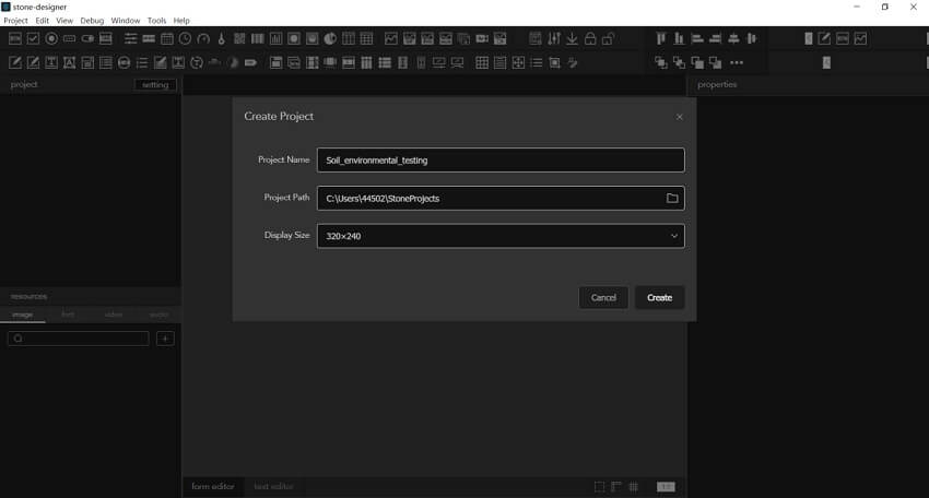
1.对于新的GUI项目,需根据屏幕尺寸选择第三个选项。本项目采用3.5英寸屏幕,因此分辨率为320×240。
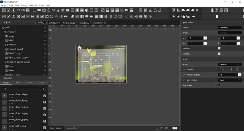
2.随后放置控制组件并添加背景图像。本项目主要使用按钮控制、标签控制、图表视图控制和图像控制。设计过程简单易用。主页左侧有两个按钮。一个用于跳转至实时参数显示页面,另一个为周数据记录页面。
在设计过程中,只需将顶部控制栏中的按钮控件拖动至中央绘图区域,然后根据需求在右侧属性区域修改背景图像或按钮效果, 微笑表情是将图像控件也拖动到中心位置,然后修改属性。效果如下:

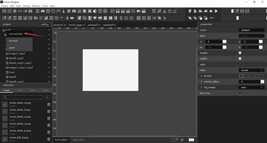
3.然后在左侧项目区域右键点击项目名称,创建一个新的空白窗口
4.上一页的设计步骤完成了部分标签控件和图像控件的布局。效果如下:

5.在第三页放置一个图表视图控件,效果如下:
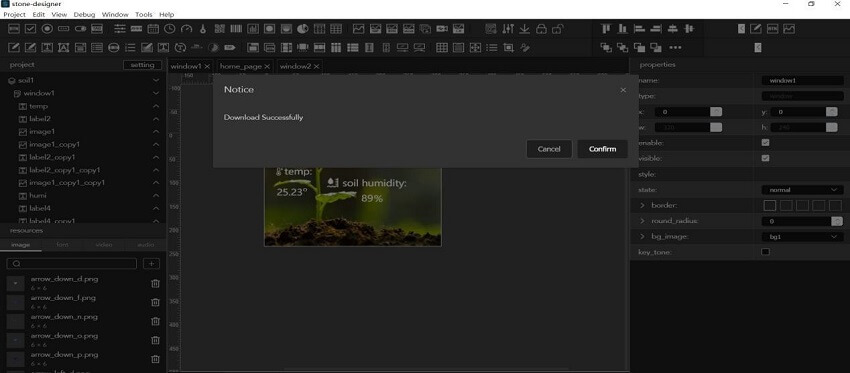
6.项目设计完成后,点击左上角调试菜单下的下载按钮,然后根据提示选择输出目录。软件将自动生成系统文件。效果如下:

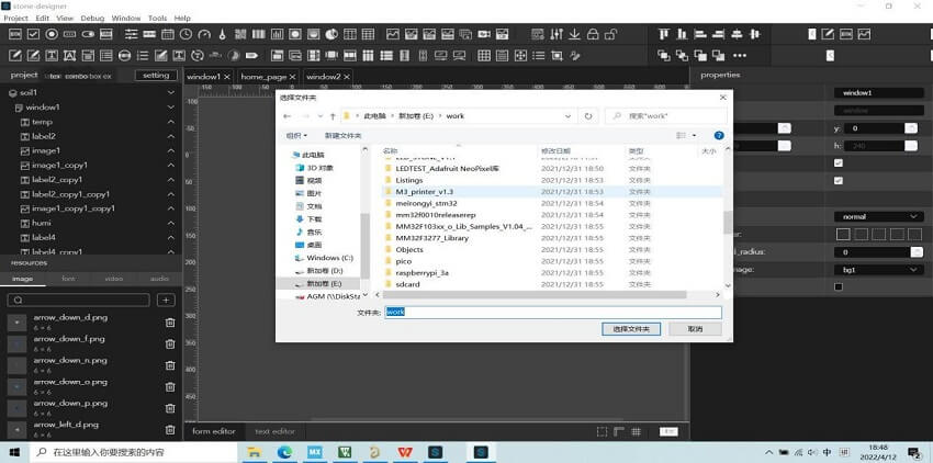
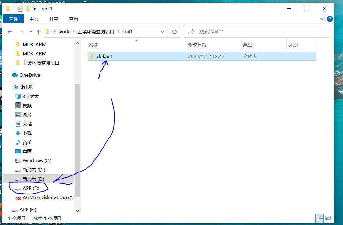
7.可将效果下载至USB接口的默认文件夹,然后输出至以下位置:
基于智能传感器的环境监测HMI解决方案 程序制作流程:
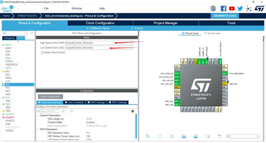
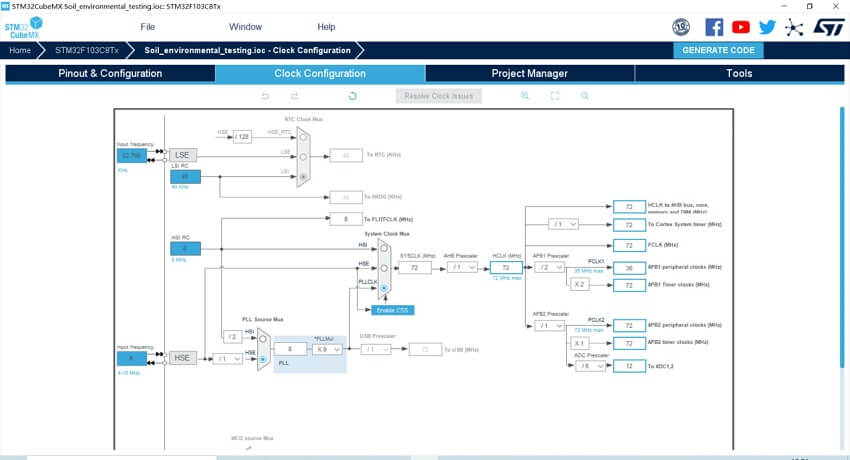
1.打开STM32CubeMX软件,选择MCU型号为STM32F103C8T6,首先配置外部高速和低速时钟源以选择RCC,然后配置时钟树,使用外部高速晶振,最大频率调制为72MHz。效果如下:
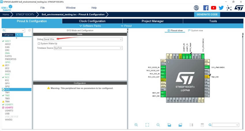
2.然后打开调试端口,效果如下:
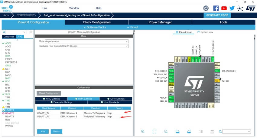
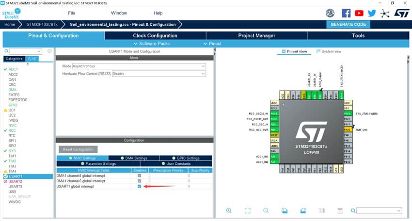
3.然后配置串口,选择USART1和异步模式,分别添加DMA通道用于TX和Rx,然后启用USART1的全局中断。其他属性保持默认,效果如下:
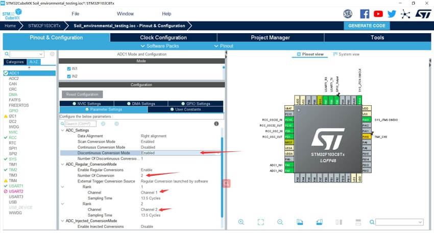
4.然后配置ADC以采集土壤湿度传感器和光敏传感器的模拟值。这两个传感器的工作电压范围为3.3V-5V,输出信号为模拟信号。因此,需打开两个ADC通道接收数据。此处打开ADC1的in1和in2通道。不使用DMA,通过间歇+扫描模式读取数据。在此配置中,需注意开启不连续转换模式并将通道数设置为2。
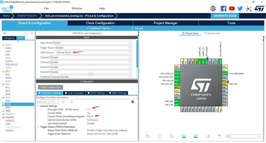
5.DHT11模块用于温度采集,驱动时需要微秒级信号。因此,可通过定时器TIM2配置一个1MHz定时器。根据之前的时钟配置,定时器时钟在APB2总线为72MHz,因此这里的前置分频频率为72-1=71,过载值设置为最大值65535。效果如下:
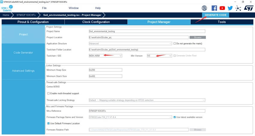
6.然后设置输出配置,选择MDK,版本V5,并生成代码。效果如下:
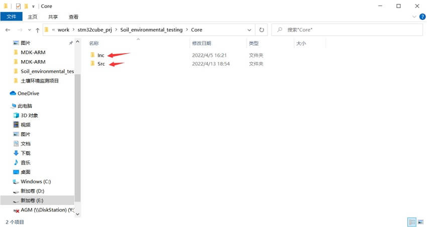
7.项目生成后,输出路径下的核心目录下有两个文件夹。Inc存储头文件,Src存储源文件。我们可以在此添加STONE串口屏幕的库文件,以便指令与屏幕之间的交互。目录如下:
8.STONE的库文件在官方网站上有链接。首先进入STONE官方网站,然后点击下图左下角的串口库链接地址,如下所示:

9.在新页面中, 可以看到相同的 Inc 和 SRC 文件夹,以及一些示例和说明。然后根据说明文档的步骤将库迁移到本地项目,链接如下:
10.由于在配置STM32CubeMX时未设置为每个外设生成独立文件,外设配置也位于主C文件中,因此主文件直接附加在C文件末尾。文档内容:
环境监测HMI设计代码:
/* USER CODE BEGIN Header */

/**

******************************************************************************

* @file           : main.c

* @brief          : Main program body

******************************************************************************

* @attention

*

* Copyright (c) 2022 STMicroelectronics.

* All rights reserved.

*

* This software is licensed under terms that can be found in the LICENSE file

* in the root directory of this software component.

* If no LICENSE file comes with this software, it is provided AS-IS.

*

******************************************************************************

*/

/* USER CODE END Header */

/* Includes ------------------------------------------------------------------*/

#include "main.h"

/* Private includes ----------------------------------------------------------*/

/* USER CODE BEGIN Includes */

#include "dht11.h"

#include "STONE.h"

/* USER CODE END Includes */

/* Private typedef -----------------------------------------------------------*/

/* USER CODE BEGIN PTD */

/* USER CODE END PTD */

/* Private define ------------------------------------------------------------*/

/* USER CODE BEGIN PD */

/* USER CODE END PD */

/* Private macro -------------------------------------------------------------*/

/* USER CODE BEGIN PM */

extern unsigned char transport_over_flage;

/* USER CODE END PM */

/* Private variables ---------------------------------------------------------*/

ADC_HandleTypeDef hadc1;

TIM_HandleTypeDef htim2;

UART_HandleTypeDef huart1;

DMA_HandleTypeDef hdma_usart1_tx;

DMA_HandleTypeDef hdma_usart1_rx;

/* USER CODE BEGIN PV */

uint8_t hal_tim1_flag;

uint32_t ADC_Value[2];

float ad1,ad2;

int ad2_32;

uint16_t temperature;

uint16_t humidity;

char humi_text[3],temp_text[4];

/* USER CODE END PV */

/* Private function prototypes -----------------------------------------------*/

void SystemClock_Config(void);

static void MX_GPIO_Init(void);

static void MX_ADC1_Init(void);

static void MX_USART1_UART_Init(void);

static void MX_DMA_Init(void);

static void MX_TIM2_Init(void);

/* USER CODE BEGIN PFP */

void delay_us(uint16_t us);

/* USER CODE END PFP */

/* Private user code ---------------------------------------------------------*/

/* USER CODE BEGIN 0 */

int humi_calc(int value){

int reference_value,value2;

reference_value = 3299;

value2 = reference_value - value;

if (value2 > 0)

{

div_t a = div(value2, 20);

if(a.quot>=100)return 100;

return a.quot;

}

else return 0;

}

/* USER CODE END 0 */

/**

* @brief  The application entry point.

* @retval int

*/

int main(void)

{

/* USER CODE BEGIN 1 */

/* USER CODE END 1 */

/* MCU Configuration--------------------------------------------------------*/

/* Reset of all peripherals, Initializes the Flash interface and the Systick. */

HAL_Init();

/* USER CODE BEGIN Init */

/* USER CODE END Init */

/* Configure the system clock */

SystemClock_Config();

/* USER CODE BEGIN SysInit */

/* USER CODE END SysInit */

/* Initialize all configured peripherals */

MX_GPIO_Init();

MX_ADC1_Init();

MX_USART1_UART_Init();

MX_DMA_Init();

MX_TIM2_Init();

/* USER CODE BEGIN 2 */

HAL_ADCEx_Calibration_Start(&hadc1);

// HAL_TIM_Base_Start_IT(&htim1);

/* USER CODE END 2 */

/* Infinite loop */

/* USER CODE BEGIN WHILE */

while(DHT11_Init()){

HAL_Delay(500);

}

while (1)

{

/* USER CODE END WHILE */

/* USER CODE BEGIN 3 */

HAL_Delay(1000);

for(uint8_t i=0;i<2;i++)

{

HAL_ADC_Start(&hadc1);

HAL_ADC_PollForConversion(&hadc1,0xffff);

ADC_Value[i]=HAL_ADC_GetValue(&hadc1);

}

HAL_ADC_Stop(&hadc1);

DHT11_Read_Data(&temperature,&humidity);

ad1 = (float)(ADC_Value[0]&0xFFF)*3.3/4096;

ad2 = (float)(ADC_Value[1]&0xFFF)*3.3/4096;

ad2_32=ad2*1000+0.5;

ad2_32=humi_calc(ad2_32);

sprintf(humi_text,"%d",ad2_32);

sprintf(temp_text,"%d",temperature>>8);

if(ad1<2)

set_text("label", "light", "light");

if(ad1>2)

set_text("label", "light", "lightless");

set_text("label", "humi", humi_text);

set_text("label", "temp", temp_text);

}

/* USER CODE END 3 */

}

/**

* @brief System Clock Configuration

* @retval None

*/

void SystemClock_Config(void)

{

RCC_OscInitTypeDef RCC_OscInitStruct = {0};

RCC_ClkInitTypeDef RCC_ClkInitStruct = {0};

RCC_PeriphCLKInitTypeDef PeriphClkInit = {0};

/** Initializes the RCC Oscillators according to the specified parameters

* in the RCC_OscInitTypeDef structure.

*/

RCC_OscInitStruct.OscillatorType = RCC_OSCILLATORTYPE_HSE;

RCC_OscInitStruct.HSEState = RCC_HSE_ON;

RCC_OscInitStruct.HSEPredivValue = RCC_HSE_PREDIV_DIV1;

RCC_OscInitStruct.HSIState = RCC_HSI_ON;

RCC_OscInitStruct.PLL.PLLState = RCC_PLL_ON;

RCC_OscInitStruct.PLL.PLLSource = RCC_PLLSOURCE_HSE;

RCC_OscInitStruct.PLL.PLLMUL = RCC_PLL_MUL9;

if (HAL_RCC_OscConfig(&RCC_OscInitStruct) != HAL_OK)

{

Error_Handler();

}

/** Initializes the CPU, AHB and APB buses clocks

*/

RCC_ClkInitStruct.ClockType = RCC_CLOCKTYPE_HCLK|RCC_CLOCKTYPE_SYSCLK

|RCC_CLOCKTYPE_PCLK1|RCC_CLOCKTYPE_PCLK2;

RCC_ClkInitStruct.SYSCLKSource = RCC_SYSCLKSOURCE_PLLCLK;

RCC_ClkInitStruct.AHBCLKDivider = RCC_SYSCLK_DIV1;

RCC_ClkInitStruct.APB1CLKDivider = RCC_HCLK_DIV2;

RCC_ClkInitStruct.APB2CLKDivider = RCC_HCLK_DIV1;

if (HAL_RCC_ClockConfig(&RCC_ClkInitStruct, FLASH_LATENCY_2) != HAL_OK)

{

Error_Handler();

}

PeriphClkInit.PeriphClockSelection = RCC_PERIPHCLK_ADC;

PeriphClkInit.AdcClockSelection = RCC_ADCPCLK2_DIV6;

if (HAL_RCCEx_PeriphCLKConfig(&PeriphClkInit) != HAL_OK)

{

Error_Handler();

}

}

/**

* @brief ADC1 Initialization Function

* @param None

* @retval None

*/

static void MX_ADC1_Init(void)

{

/* USER CODE BEGIN ADC1_Init 0 */

/* USER CODE END ADC1_Init 0 */

ADC_ChannelConfTypeDef sConfig = {0};

/* USER CODE BEGIN ADC1_Init 1 */

/* USER CODE END ADC1_Init 1 */

/** Common config

*/

hadc1.Instance = ADC1;

hadc1.Init.ScanConvMode = ADC_SCAN_ENABLE;

hadc1.Init.ContinuousConvMode = DISABLE;

hadc1.Init.DiscontinuousConvMode = ENABLE;

hadc1.Init.NbrOfDiscConversion = 1;

hadc1.Init.ExternalTrigConv = ADC_SOFTWARE_START;

hadc1.Init.DataAlign = ADC_DATAALIGN_RIGHT;

hadc1.Init.NbrOfConversion = 2;

if (HAL_ADC_Init(&hadc1) != HAL_OK)

{

Error_Handler();

}

/** Configure Regular Channel

*/

sConfig.Channel = ADC_CHANNEL_1;

sConfig.Rank = ADC_REGULAR_RANK_1;

sConfig.SamplingTime = ADC_SAMPLETIME_13CYCLES_5;

if (HAL_ADC_ConfigChannel(&hadc1, &sConfig) != HAL_OK)

{

Error_Handler();

}

/** Configure Regular Channel

*/

sConfig.Channel = ADC_CHANNEL_2;

sConfig.Rank = ADC_REGULAR_RANK_2;

if (HAL_ADC_ConfigChannel(&hadc1, &sConfig) != HAL_OK)

{

Error_Handler();

}

/* USER CODE BEGIN ADC1_Init 2 */

/* USER CODE END ADC1_Init 2 */

}

/**

* @brief TIM2 Initialization Function

* @param None

* @retval None

*/

static void MX_TIM2_Init(void)

{

/* USER CODE BEGIN TIM2_Init 0 */

/* USER CODE END TIM2_Init 0 */

TIM_ClockConfigTypeDef sClockSourceConfig = {0};

TIM_MasterConfigTypeDef sMasterConfig = {0};

/* USER CODE BEGIN TIM2_Init 1 */

/* USER CODE END TIM2_Init 1 */

htim2.Instance = TIM2;

htim2.Init.Prescaler = 71;

htim2.Init.CounterMode = TIM_COUNTERMODE_UP;

htim2.Init.Period = 65535;

htim2.Init.ClockDivision = TIM_CLOCKDIVISION_DIV1;

htim2.Init.AutoReloadPreload = TIM_AUTORELOAD_PRELOAD_DISABLE;

if (HAL_TIM_Base_Init(&htim2) != HAL_OK)

{

Error_Handler();

}

sClockSourceConfig.ClockSource = TIM_CLOCKSOURCE_INTERNAL;

if (HAL_TIM_ConfigClockSource(&htim2, &sClockSourceConfig) != HAL_OK)

{

Error_Handler();

}

sMasterConfig.MasterOutputTrigger = TIM_TRGO_RESET;

sMasterConfig.MasterSlaveMode = TIM_MASTERSLAVEMODE_DISABLE;

if (HAL_TIMEx_MasterConfigSynchronization(&htim2, &sMasterConfig) != HAL_OK)

{

Error_Handler();

}

/* USER CODE BEGIN TIM2_Init 2 */

/* USER CODE END TIM2_Init 2 */

}

/**

* @brief USART1 Initialization Function

* @param None

* @retval None

*/

static void MX_USART1_UART_Init(void)

{

/* USER CODE BEGIN USART1_Init 0 */

/* USER CODE END USART1_Init 0 */

/* USER CODE BEGIN USART1_Init 1 */

/* USER CODE END USART1_Init 1 */

huart1.Instance = USART1;

huart1.Init.BaudRate = 115200;

huart1.Init.WordLength = UART_WORDLENGTH_8B;

huart1.Init.StopBits = UART_STOPBITS_1;

huart1.Init.Parity = UART_PARITY_NONE;

huart1.Init.Mode = UART_MODE_TX_RX;

huart1.Init.HwFlowCtl = UART_HWCONTROL_NONE;

huart1.Init.OverSampling = UART_OVERSAMPLING_16;

if (HAL_UART_Init(&huart1) != HAL_OK)

{

Error_Handler();

}

/* USER CODE BEGIN USART1_Init 2 */

/* USER CODE END USART1_Init 2 */

}

/**

* Enable DMA controller clock

*/

static void MX_DMA_Init(void)

{

/* DMA controller clock enable */

__HAL_RCC_DMA1_CLK_ENABLE();

/* DMA interrupt init */

/* DMA1_Channel4_IRQn interrupt configuration */

HAL_NVIC_SetPriority(DMA1_Channel4_IRQn, 0, 0);

HAL_NVIC_EnableIRQ(DMA1_Channel4_IRQn);

/* DMA1_Channel5_IRQn interrupt configuration */

HAL_NVIC_SetPriority(DMA1_Channel5_IRQn, 0, 0);

HAL_NVIC_EnableIRQ(DMA1_Channel5_IRQn);

}

/**

* @brief GPIO Initialization Function

* @param None

* @retval None

*/

static void MX_GPIO_Init(void)

{

GPIO_InitTypeDef GPIO_InitStruct = {0};

/* GPIO Ports Clock Enable */

__HAL_RCC_GPIOC_CLK_ENABLE();

__HAL_RCC_GPIOD_CLK_ENABLE();

__HAL_RCC_GPIOA_CLK_ENABLE();

__HAL_RCC_GPIOB_CLK_ENABLE();

/*Configure GPIO pin Output Level */

HAL_GPIO_WritePin(GPIOB, GPIO_PIN_5, GPIO_PIN_SET);

/*Configure GPIO pin : PA10 */

GPIO_InitStruct.Pin = GPIO_PIN_10;

GPIO_InitStruct.Mode = GPIO_MODE_AF_PP;

GPIO_InitStruct.Speed = GPIO_SPEED_FREQ_LOW;

HAL_GPIO_Init(GPIOA, &GPIO_InitStruct);

/*Configure GPIO pin : PB5 */

GPIO_InitStruct.Pin = GPIO_PIN_5;

GPIO_InitStruct.Mode = GPIO_MODE_OUTPUT_PP;

GPIO_InitStruct.Pull = GPIO_PULLDOWN;

GPIO_InitStruct.Speed = GPIO_SPEED_FREQ_HIGH;

HAL_GPIO_Init(GPIOB, &GPIO_InitStruct);

}

/* USER CODE BEGIN 4 */

void HAL_UART_TxCpltCallback(UART_HandleTypeDef *huart)

{

if (STONE_uart_get_flag(USER_UART))

transport_over_flage = 1;

}

void delay_us(uint16_t us){

uint16_t differ = 0xffff-us-5;

__HAL_TIM_SET_COUNTER(&htim2,differ);

HAL_TIM_Base_Start(&htim2);

while(differ < 0xffff-5){

differ = __HAL_TIM_GET_COUNTER(&htim2);

}

HAL_TIM_Base_Stop(&htim2);

}

//void HAL_TIM_PeriodElapsedCallback(TIM_HandleTypeDef *htim)

//{

//    if (htim == (&htim1)) //1s

//    {

//// DHT11_Read_Data(&temperature,&humidity);

// for(uint8_t i=0;i<2;i++)

//      {

//          HAL_ADC_Start(&hadc1);

//          HAL_ADC_PollForConversion(&hadc1,0xffff);

//          ADC_Value[i]=HAL_ADC_GetValue(&hadc1);

//      }

// HAL_ADC_Stop(&hadc1);

// ad1 = (float)(ADC_Value[0]&0xFFF)*3.3/4096;

// ad2 = (float)(ADC_Value[1]&0xFFF)*3.3/4096;

// hal_tim1_flag = 1;

//    }

//}

/* USER CODE END 4 */

/**

* @brief  This function is executed in case of error occurrence.

* @retval None

*/

void Error_Handler(void)

{

/* USER CODE BEGIN Error_Handler_Debug */

/* User can add his own implementation to report the HAL error return state */

__disable_irq();

while (1)

{

}

/* USER CODE END Error_Handler_Debug */

}

#ifdef  USE_FULL_ASSERT

/**

* @brief  Reports the name of the source file and the source line number

*         where the assert_param error has occurred.

* @param  file: pointer to the source file name

* @param  line: assert_param error line source number

* @retval None

*/

void assert_failed(uint8_t *file, uint32_t line)

{

/* USER CODE BEGIN 6 */

/* User can add his own implementation to report the file name and line number,

ex: printf("Wrong parameters value: file %s on line %d\r\n", file, line) */

/* USER CODE END 6 */

}

#endif /* USE_FULL_ASSERT */