aa
STONE LCD 车载仪表盘串口屏
注意事项:该 10.1 英寸 LCD 车载仪表盘串口屏与 STONE LCD 串口屏结合 RTL8762CJF MCU 用于开发和制造车载显示仪表盘。
简介
在日常用车过程中,我们需要随时了解车辆状态,以避免损坏车辆重要部件,同时消除潜在危险。仪表盘上显示的信息是了解车辆状态的重要方式。
此次我将使用10.1英寸TFT LCD屏幕制作车载显示仪表盘。众所周知,STONE智能串口屏的开发便捷快速,无需过多繁琐的操作步骤。这不仅适合大多数学习爱好者,在实际项目中还能加快开发速度,节省开发时间,快速占领市场。
我使用更常见的RTL8762CJF SCM进行开发,通过IIC或串口实现将数据上传至TFT LCD屏幕。此次还将使用语音广播功能,为驾驶员提供更好的模拟体验。
LCD屏幕汽车仪表盘项目功能
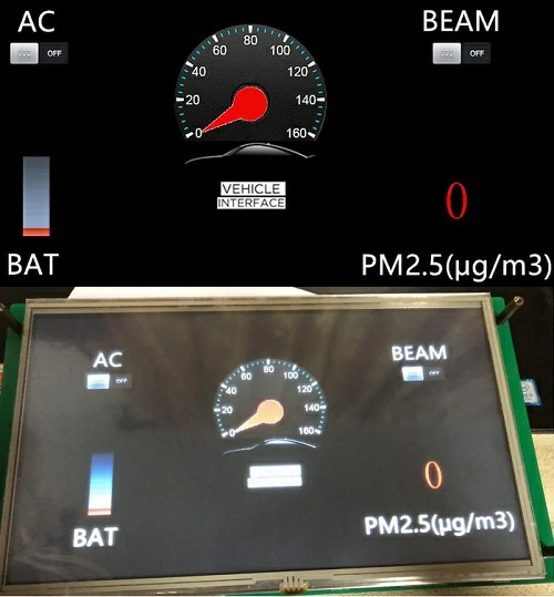
这里需要实现一个二手车显示项目,项目主要通过触摸调节、微控制器上传指令的方式,模拟按钮操作。当MCU按下按钮时,通过串口命令将指令发送至STVC101WT-01串口接口屏幕,屏幕将自动解析数据并显示在LCD屏幕上。同时,屏幕上还设有按钮功能,可实现串口指令,从而控制MCU。
总结,五项功能
- 串口屏幕实现位图显示功能;
- 实现拨号旋转功能;
- 实现触摸指令发送;
- 实现语音广播;
- 实现数据指令上传。
功能确定后,进行模块选型:
- 触摸屏型号;
- 选用何种MCU模块;
- 语音广播模块。
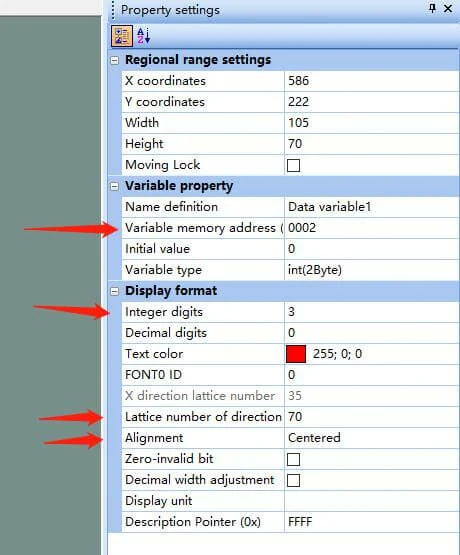
在配置数字文本框时,会依次显示以下界面:
设置控制变量地址;硬件介绍与原理
扬声器
由于STONE串口屏幕自带音频驱动并预留了对应接口,因此可使用最常见的磁铁扬声器,俗称喇叭。扬声器是一种将电信号转换为声信号的换能器。扬声器是音响设备中最脆弱的组件之一,也是实现声音效果最重要的组件之一。扬声器的种类繁多,价格差异较大。音频电能通过使纸盆或振膜振动并通过电磁、压电或静电效应与周围空气共振(共鸣)来产生声音。
购买链接: http://dwz.date/afdC
STONETOOL Box开发步骤
一般来说,只有三个步骤:
- 使用TOOL2019上层计算机软件设计;
- MCU和屏幕通信开发;
- 音频文件制作和导入。
STONE TOOL的安装
TOOL可从官方网站 https://www.stone-hmi.com/ 下载,同时下载相关USB串口驱动程序。
KEIL的安装
1、下载链接:https://pan.baidu.com/s/1smropvXeXKXw413W_-rvtw
2、下载并解压
解压后打开文件夹
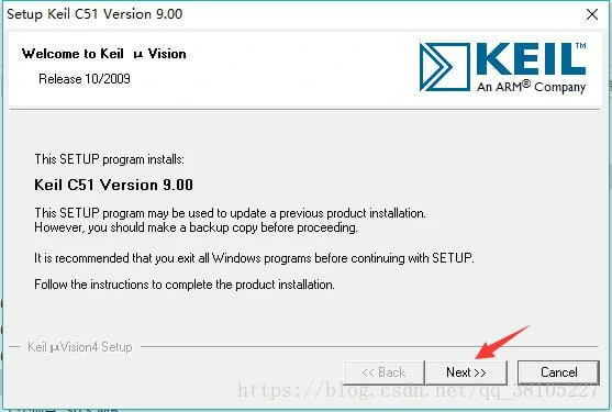
4、双击文件 c51v900.exe,并在对话框中点击“下一步”。

Open the folder after unzipping
STVC101WT-01 串口 LCD 屏幕描述
- 10.1英寸 1024×600 工业级 TFT 面板和 4 线电阻式触摸屏;
- 亮度 300cd/m²;
- LED 背光;
- RGB 颜色 65k;
- 可见区域为 222.7mm × 125.3mm;
- 视角 70/70/50/60;
- 工作寿命 20,000 小时。
- 32 位 Cortex-M4 200Hz CPU;
- CPLD EPM240 TFT-LCD 控制器;
- 128MB(或 1GB)闪存;
- USB 接口(U 盘)下载;
- 图形用户界面设计工具箱软件;
- 简单而强大的十六进制指令集。
基本功能
- 8MB-128MB 闪存空间,SDWe 系列 128MB,SDWa 系列 8MB/16MB;
- 支持硬件 JPG 解码,存储更高效,显示更快;
- 支持 U 盘离线批量下载,有效提升批量下载效率,降低操作人员的专业技术要求;
- 256 字节寄存器空间;
- 64K字(128K字节)变量存储空间,8通道曲线存储,变量显示速度极快(80ms)
- 响应速度;
- 支持每页显示多达128个变量;
- 集成实时时钟RTC,支持触摸蜂鸣器声音功能;
- 支持软件90度、180度、270度屏幕旋转,调整合适的视觉角度;
- 支持背光亮度调节,自动待机屏保功能;
- 支持外部矩阵键盘;
- 支持音频和视频播放;
- 行业领先的电磁辐射指标,助您轻松应对Class B标准;
- 文件名命名规则简单,无需对应Flash块编号,也无需繁琐的手动分配Flash块功能;
- 支持虚拟串口屏幕功能。
STONE STVC101WT – 01显示模块通过串口与MCU通信,本项目中需使用该模块,仅需通过PC设计良好的UI界面,通过菜单栏选项按钮、文本框、背景图片及逻辑页面进行添加,生成配置文件后下载至串口屏即可运行。
RTL8762C EVB简介
8762C 评估板为客户提供硬件开发环境,包括:
- 电源转换模块;
- 26 轴运动传感器;
- 4 个 LED 和 6 个按钮;
- 纽扣电池和锂电池座;
- USB 转 UART 转换芯片,FT232RL。
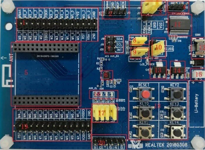
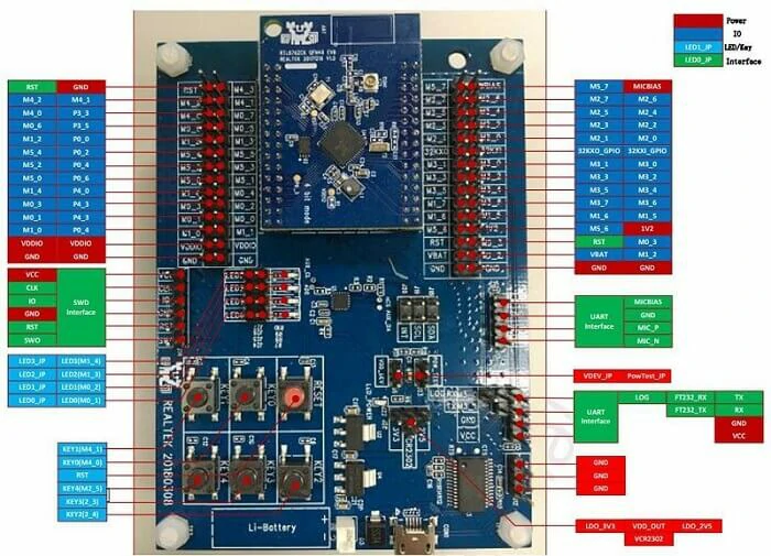
评估板模块及接口分布
评估板模块的详细描述
评估板模块及接口分布,请参见下图:
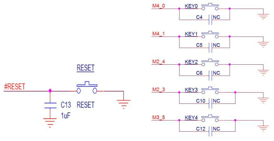
按键
共有复位按键和5组独立按键,
如图所示:
主芯片8762 c
- 灵活的GPIO设计
- 硬件按键扫描和解码器
- 嵌入式红外收发器
- 实时时钟(RTC)
- SPI主控/从 x 2;定时器 x 8;I2C x 2;PWM x 8;UART x 2
- 400千采样率,12位,8通道AUXADC
- I2S接口用于外部音频编解码器
- I8080接口用于LCD
- 内部32K RCOSC保持BLE连接
- 嵌入式PGA和音频ADC带5段均衡器
石器工具 2019 界面设计
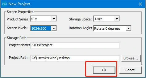
使用已安装的 TOOL 2019,点击左上角的“新建项目”,然后点击“确定”。
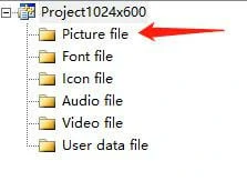
系统默认生成一个蓝色背景的项目。选中该项目,右键点击并选择“删除”以移除背景。接着右键点击图片文件并选择“添加”以添加自定义图片背景,如下所示:
如下:
选择对应的背景图片。
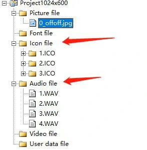
以相同方式添加位图文件和音频文件至项目。
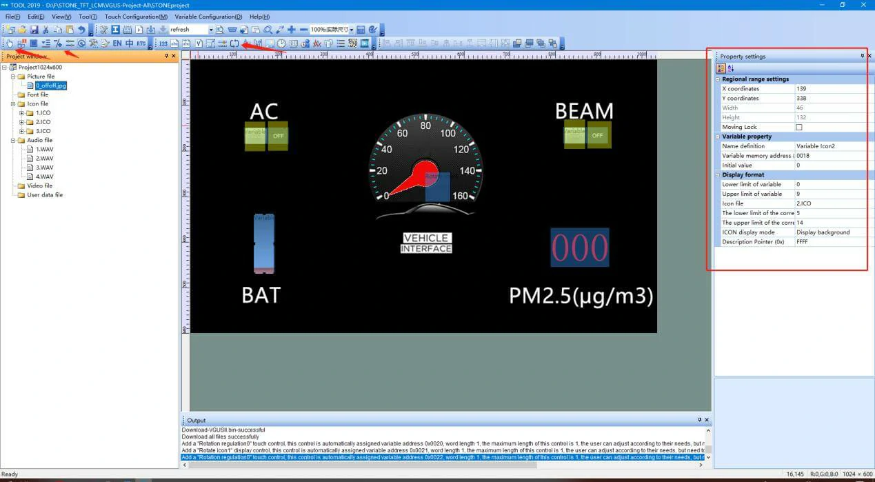
随后添加所需控件,主要包括按钮控件、数字加减控件及数据变量控件。
然后配置每个控件的变量地址,这里我们有以下配置:
- 空调按钮地址配置为0x000C;
- 远光灯按钮地址配置为0x000D;
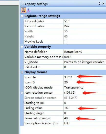
- 速度拨号地址配置为0x001B;
- 电力图标地址配置为0x0018;
- PM2.5地址配置为0x001C;
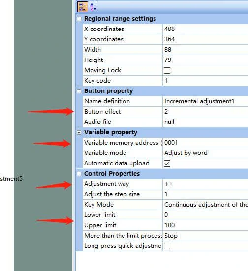
当按钮配置完成后,会显示以下界面:
- 配置按钮按下效果;
- 配置变量地址的控制,用于写入其值;
- 配置加减操作;
- 配置值的范围。
设置位数;
设置数字大小;
设置对齐方式。
配置速度表时,依次显示以下内容:
选择库文件;
在库文件中指定要使用的文件;
设置指针图标周围的中心坐标;
设置指针的旋转范围;
设置指针的旋转角度。
最后,点击构建配置工具。
注意:
控制按钮通过变量地址与对应的位图关联,因此需保持一致性以实现正确控制。
因此,串口指令如下:
电池:0xA5,0x5A,0x05,0x82,0x00,0x18,0x00,0x00
速度:0xA5,0x5A,0x05,0x82,0x00,0x1B,0x00,0x00
PM2.5:0xA5,0x5A,0x05,0x82,0x00,0x1C,0x00,0x00
RTL8762C 的开发
打开 KEIL 并导入我们的项目文件,如图所示:
由于这是第一次使用,需要相应调整 FLASH 算法:
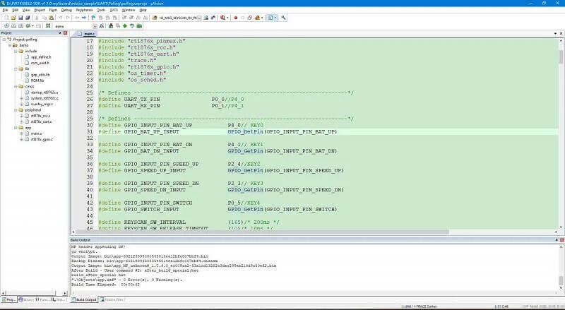

由于这里使用了按钮控制,因此需要在代码中进行以下修改:
/*** @file main.c* @brief uart demo polling tx and rx.* @details* @author wangzex* @date 2018-06-28* @version v0.1**********************************************************************************************************//* Includes ------------------------------------------------------------------*/#include#include "rtl876x_nvic.h"#include "rtl876x_pinmux.h"#include "rtl876x_rcc.h"#include "rtl876x_uart.h"#include "trace.h"#include "rtl876x_gpio.h"#include "os_timer.h"#include "os_sched.h"/* Defines ------------------------------------------------------------------*/#define UART_TX_PIN P0_0//P4_0#define UART_RX_PIN P0_1//P4_1/* Defines ------------------------------------------------------------------*/#define GPIO_INPUT_PIN_BAT_UP P4_0// KEY0#define GPIO_BAT_UP_INPUT GPIO_GetPin(GPIO_INPUT_PIN_BAT_UP)#define GPIO_INPUT_PIN_BAT_DN P4_1// KEY1#define GPIO_BAT_DN_INPUT GPIO_GetPin(GPIO_INPUT_PIN_BAT_DN)#define GPIO_INPUT_PIN_SPEED_UP P2_4//KEY2#define GPIO_SPEED_UP_INPUT GPIO_GetPin(GPIO_INPUT_PIN_SPEED_UP)#define GPIO_INPUT_PIN_SPEED_DN P2_3// KEY3#define GPIO_SPEED_DN_INPUT GPIO_GetPin(GPIO_INPUT_PIN_SPEED_DN)#define GPIO_INPUT_PIN_SWITCH P0_5//KEY4#define GPIO_SWITCH_INPUT GPIO_GetPin(GPIO_INPUT_PIN_SWITCH)#define KEYSCAN_SW_INTERVAL (165)/* 200ms */#define KEYSCAN_SW_RELEASE_TIMEOUT (10)/* 10ms */uint8_t data_buf_bat[] = {0xA5, 0x5A, 0x05, 0x82, 0x00, 0x18, 0x00, 0x00};uint8_t data_buf_speed[] = {0xA5, 0x5A, 0x05, 0x82, 0x00, 0x1B, 0x00, 0x00};uint8_t data_buf_pm25[] = {0xA5, 0x5A, 0x05, 0x82, 0x00, 0x1C, 0x00, 0x00};//the last byte is datavoid *KeyScan_Timer_Handle = NULL;void timer_keyscan_callback(void *p_xTimer){uint8_t gpio_input_data_level = 0;gpio_input_data_level = GPIO_ReadInputDataBit(GPIO_BAT_UP_INPUT);//KEY0DBG_DIRECT("GPIO_BAT_UP_INPUT = %d\n", gpio_input_data_level);if(!gpio_input_data_level){gpio_input_data_level = GPIO_ReadInputDataBit(GPIO_SWITCH_INPUT);//KEY0DBG_DIRECT("GPIO_BAT_UP_INPUT = %d\n", gpio_input_data_level);if(!gpio_input_data_level){data_buf_pm25[7] ++;UART_SendData(UART, data_buf_pm25, 8);}else{data_buf_bat[7] ++;UART_SendData(UART, data_buf_bat, 8);}}gpio_input_data_level = GPIO_ReadInputDataBit(GPIO_BAT_DN_INPUT);//KEY0DBG_DIRECT("GPIO_BAT_UP_INPUT = %d\n", gpio_input_data_level);if(!gpio_input_data_level){gpio_input_data_level = GPIO_ReadInputDataBit(GPIO_SWITCH_INPUT);//KEY0DBG_DIRECT("GPIO_BAT_UP_INPUT = %d\n", gpio_input_data_level);if(!gpio_input_data_level){data_buf_pm25[7] --;UART_SendData(UART, data_buf_pm25, 8);}else{data_buf_bat[7] --;UART_SendData(UART, data_buf_bat, 8);}}gpio_input_data_level = GPIO_ReadInputDataBit(GPIO_SPEED_UP_INPUT);//KEY0DBG_DIRECT("GPIO_BAT_UP_INPUT = %d\n", gpio_input_data_level);if(!gpio_input_data_level){data_buf_speed[7] ++;UART_SendData(UART, data_buf_speed, 8);}gpio_input_data_level = GPIO_ReadInputDataBit(GPIO_SPEED_DN_INPUT);//KEY0DBG_DIRECT("GPIO_BAT_UP_INPUT = %d\n", gpio_input_data_level);if(!gpio_input_data_level){data_buf_speed[7] --;UART_SendData(UART, data_buf_speed, 8);}// gpio_input_data_level = GPIO_ReadInputDataBit(GPIO_PM25_INPUT);//KEY0// DBG_DIRECT("GPIO_BAT_UP_INPUT = %d\n", gpio_input_data_level);// if(!gpio_input_data_level)// {// data_buf_pm25[7] --;// UART_SendData(UART, data_buf_pm25, 8);// }os_timer_restart(&KeyScan_Timer_Handle, KEYSCAN_SW_INTERVAL);}void timer_keyscan_init(void){DBG_DIRECT("[io_keyscan] timer_keyscan_init: keyscan timer init");if (false == os_timer_create(&KeyScan_Timer_Handle, "keyscan_timer", 1, \KEYSCAN_SW_INTERVAL, false, timer_keyscan_callback)){DBG_DIRECT("[io_keyscan] timer_keyscan_init: timer creat failed!");}os_timer_start(&KeyScan_Timer_Handle);}/** @brief UART_BaudRate_Table* div ovsr ovsr_adj :These three parameters set the baud rate calibration parameters of UART.baudrate | div | ovsr | ovsr_adj--------------------------------------------------------1200Hz | 2589 | 7 | 0x7F79600Hz | 271 | 10 | 0x24A14400Hz | 271 | 5 | 0x22219200Hz | 165 | 7 | 0x5AD28800Hz | 110 | 7 | 0x5AD38400Hz | 85 | 7 | 0x22257600Hz | 55 | 7 | 0x5AD76800Hz | 35 | 9 | 0x7EF115200Hz | 20 | 12 | 0x252128000Hz | 25 | 7 | 0x555153600Hz | 15 | 12 | 0x252230400Hz | 10 | 12 | 0x252460800Hz | 5 | 12 | 0x252500000Hz | 8 | 5 | 0921600Hz | 4 | 5 | 0x3F71000000Hz | 4 | 5 | 01382400Hz | 2 | 9 | 0x2AA1444400Hz | 2 | 8 | 0x5F71500000Hz | 2 | 8 | 0x4921843200Hz | 2 | 5 | 0x3F72000000Hz | 2 | 5 | 02100000Hz | 1 | 14 | 0x4002764800Hz | 1 | 9 | 0x2AA3000000Hz | 1 | 8 | 0x4923250000Hz | 1 | 7 | 0x1123692300Hz | 1 | 5 | 0x5F73750000Hz | 1 | 5 | 0x36D4000000Hz | 1 | 5 | 06000000Hz | 1 | 1 | 0x36D-----------------------------------------------------*/ /* End of UART_BaudRate_Table *//* Globals ------------------------------------------------------------------*/typedef struct{uint16_t div;uint16_t ovsr;uint16_t ovsr_adj;} UART_BaudRate_TypeDef;const UART_BaudRate_TypeDef BaudRate_Table[10] ={{271, 10, 0x24A}, // BAUD_RATE_9600{165, 7, 0x5AD}, // BAUD_RATE_19200{20, 12, 0x252}, // BAUD_RATE_115200{10, 12, 0x252}, // BAUD_RATE_230400{5, 12, 0x252}, // BAUD_RATE_460800{4, 5, 0x3F7}, // BAUD_RATE_921600{2, 5, 0}, // BAUD_RATE_2000000{1, 8, 0x492}, // BAUD_RATE_3000000{1, 5, 0}, // BAUD_RATE_4000000{1, 1, 0x36D}, // BAUD_RATE_6000000};void board_gpio_init(void){Pad_Config(GPIO_INPUT_PIN_BAT_UP, PAD_PINMUX_MODE, PAD_IS_PWRON, PAD_PULL_UP, PAD_OUT_DISABLE,PAD_OUT_HIGH);Pinmux_Config(GPIO_INPUT_PIN_BAT_UP, DWGPIO);Pad_Config(GPIO_INPUT_PIN_BAT_DN, PAD_PINMUX_MODE, PAD_IS_PWRON, PAD_PULL_UP, PAD_OUT_DISABLE,PAD_OUT_HIGH);Pinmux_Config(GPIO_INPUT_PIN_BAT_DN, DWGPIO);Pad_Config(GPIO_INPUT_PIN_SPEED_UP, PAD_PINMUX_MODE, PAD_IS_PWRON, PAD_PULL_UP, PAD_OUT_DISABLE,PAD_OUT_HIGH);Pinmux_Config(GPIO_INPUT_PIN_SPEED_UP, DWGPIO);Pad_Config(GPIO_INPUT_PIN_SPEED_DN, PAD_PINMUX_MODE, PAD_IS_PWRON, PAD_PULL_UP, PAD_OUT_DISABLE,PAD_OUT_HIGH);Pinmux_Config(GPIO_INPUT_PIN_SPEED_DN, DWGPIO);Pad_Config(GPIO_INPUT_PIN_SWITCH, PAD_PINMUX_MODE, PAD_IS_PWRON, PAD_PULL_UP, PAD_OUT_DISABLE,PAD_OUT_HIGH);Pinmux_Config(GPIO_INPUT_PIN_SWITCH, DWGPIO);}uint8_t String_Buf[100];/*** @brief Initialization of pinmux settings and pad settings.* @param No parameter.* @return void*/void board_uart_init(void){Pad_Config(UART_TX_PIN, PAD_PINMUX_MODE, PAD_IS_PWRON, PAD_PULL_UP, PAD_OUT_DISABLE, PAD_OUT_HIGH);Pad_Config(UART_RX_PIN, PAD_PINMUX_MODE, PAD_IS_PWRON, PAD_PULL_UP, PAD_OUT_DISABLE, PAD_OUT_HIGH);Pinmux_Config(UART_TX_PIN, UART0_TX);Pinmux_Config(UART_RX_PIN, UART0_RX);}/*** @brief Initialize GPIO peripheral.* @param No parameter.* @return void*/void driver_gpio_init(void){/* Initialize GPIO peripheral */RCC_PeriphClockCmd(APBPeriph_GPIO, APBPeriph_GPIO_CLOCK, ENABLE);GPIO_InitTypeDef GPIO_InitStruct;GPIO_StructInit(&GPIO_InitStruct);GPIO_InitStruct.GPIO_Pin = GPIO_INPUT_PIN_BAT_UP;GPIO_InitStruct.GPIO_Mode = GPIO_Mode_IN;GPIO_InitStruct.GPIO_ITCmd = DISABLE;GPIO_Init(&GPIO_InitStruct);GPIO_InitStruct.GPIO_Pin = GPIO_INPUT_PIN_BAT_DN;GPIO_Init(&GPIO_InitStruct);GPIO_InitStruct.GPIO_Pin = GPIO_INPUT_PIN_SPEED_UP;GPIO_Init(&GPIO_InitStruct);GPIO_InitStruct.GPIO_Pin = GPIO_INPUT_PIN_SPEED_DN;GPIO_Init(&GPIO_InitStruct);GPIO_InitStruct.GPIO_Pin = GPIO_INPUT_PIN_SWITCH;GPIO_Init(&GPIO_InitStruct);}/*** @brief Demo code of operation about gpio.* @param No parameter.* @return void*/void gpio_demo(void){/* Configure pad and pinmux firstly! */board_gpio_init();/* Initialize gpio peripheral */driver_gpio_init();}/*** @brief Initialize uart peripheral.* @param No parameter.* @return void*/void driver_uart_init(void){UART_DeInit(UART);RCC_PeriphClockCmd(APBPeriph_UART0, APBPeriph_UART0_CLOCK, ENABLE);/* uart init */UART_InitTypeDef UART_InitStruct;UART_StructInit(&UART_InitStruct);/* Config uart baudrate */UART_InitStruct.div = BaudRate_Table[BAUD_RATE_115200].div;UART_InitStruct.ovsr = BaudRate_Table[BAUD_RATE_115200].ovsr;UART_InitStruct.ovsr_adj = BaudRate_Table[BAUD_RATE_115200].ovsr_adj;UART_InitStruct.parity = UART_PARITY_NO_PARTY;UART_InitStruct.stopBits = UART_STOP_BITS_1;UART_InitStruct.wordLen = UART_WROD_LENGTH_8BIT;UART_InitStruct.rxTriggerLevel = 16; //1~29UART_InitStruct.idle_time = UART_RX_IDLE_2BYTE; //idle interrupt wait timeUART_Init(UART, &UART_InitStruct);}/*** @brief UARt send data continuous.* @param No parameter.* @return void*/void uart_senddata_continuous(UART_TypeDef *UARTx, const uint8_t *pSend_Buf, uint16_t vCount){uint8_t count;while (vCount / UART_TX_FIFO_SIZE > 0){while (UART_GetFlagState(UARTx, UART_FLAG_THR_EMPTY) == 0);for (count = UART_TX_FIFO_SIZE; count > 0; count--){UARTx->RB_THR = *pSend_Buf++;}vCount -= UART_TX_FIFO_SIZE;}while (UART_GetFlagState(UARTx, UART_FLAG_THR_EMPTY) == 0);while (vCount--){UARTx->RB_THR = *pSend_Buf++;}}/*** @brief Demo code of uart.* @param No parameter.* @return void*/void uart_demo(void){uint16_t demo_str_len = 0;// uint8_t rx_byte = 0;board_uart_init();driver_uart_init();char *demo_str = "### Uart demo polling read uart data ###\r\n";demo_str_len = strlen(demo_str);memcpy(String_Buf, demo_str, demo_str_len);/* Send demo tips */uart_senddata_continuous(UART, String_Buf, demo_str_len);/* Loop rx and tx */// while (1)// {// if (UART_GetFlagState(UART, UART_FLAG_RX_DATA_RDY) == SET)// {// rx_byte = UART_ReceiveByte(UART);// UART_SendByte(UART, rx_byte);// }// }}/*** @brief Entry of app code* @return int (To avoid compile warning)*/int main(void){uart_demo();gpio_demo();timer_keyscan_init();os_sched_start();return 0;}
Finally, just connect the MCU to the serial port LCD screen LCD for the car dashboard
and connect the speaker to demonstrate.