项目中使用的耗材
显示屏采用8英寸显示屏和8英寸智能STONE串口屏工业显示模块
STONE STVI080WT-01 串口屏
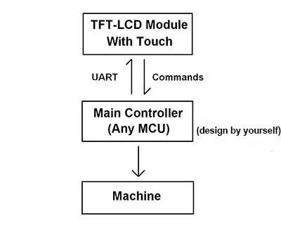
STONESTVI080WT-01智能TFTLCD模块搭载Cortex-M4 32位CPU,可通过UART端口使用简单十六进制指令由任意MCU控制。
STONE为软件工程师提供了多种图形人机交互界面功能的简单直观设置,包括文本、数字、曲线、图像切换、键盘、进度条、滑块、旋钮、时钟和触摸按钮,以及数据存储、USB下载、视频和音频功能。
工程师可轻松将STONE串口屏的彩色人机交互界面和触摸功能应用于各类工业设备,大幅缩短开发时间和成本。
易于使用:
- 设计一套美观的“图形人机交互界面”,并使用我们的工具箱软件在 GUI 上设置各种应用功能。
- 通过 RS232、RS485 或 TTL 接口直接连接客户 MCU,即插即用。
- 编译MCU程序并通过4条简单的十六进制指令控制STONE串口屏模块。
继电器模块 – 8通道

继电器板使用说明:
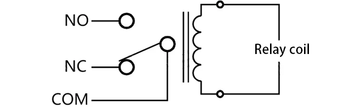
当继电器线圈两端无电压或电压不足时,继电器公共端(COM)与常闭端导通
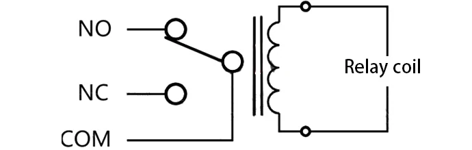
当继电器线圈两端电压达到吸合电压时,继电器公共端(COM)与常开端导通

电气设备安装与改造方法
该模块采用贴片光耦隔离,具有强抗干扰能力。共有8种控制方式,从IN1到IN8
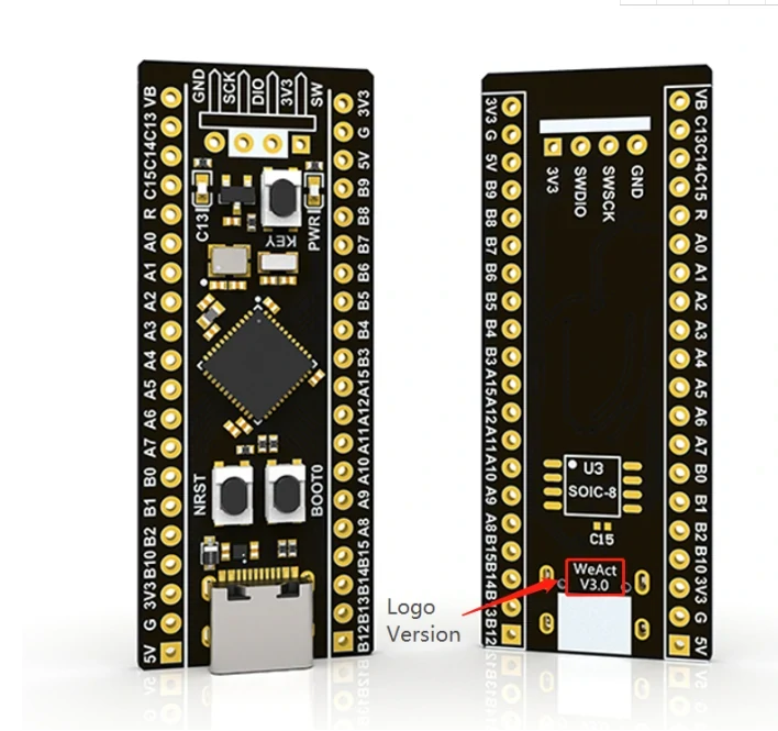
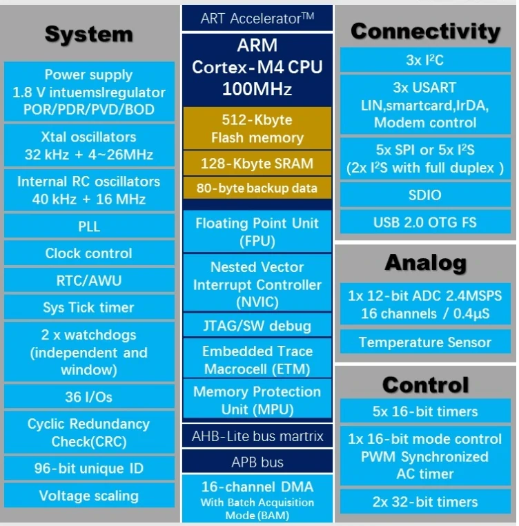
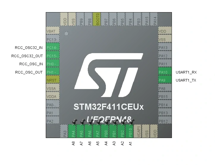
STM32F411 MCU核心板
STM32核心板
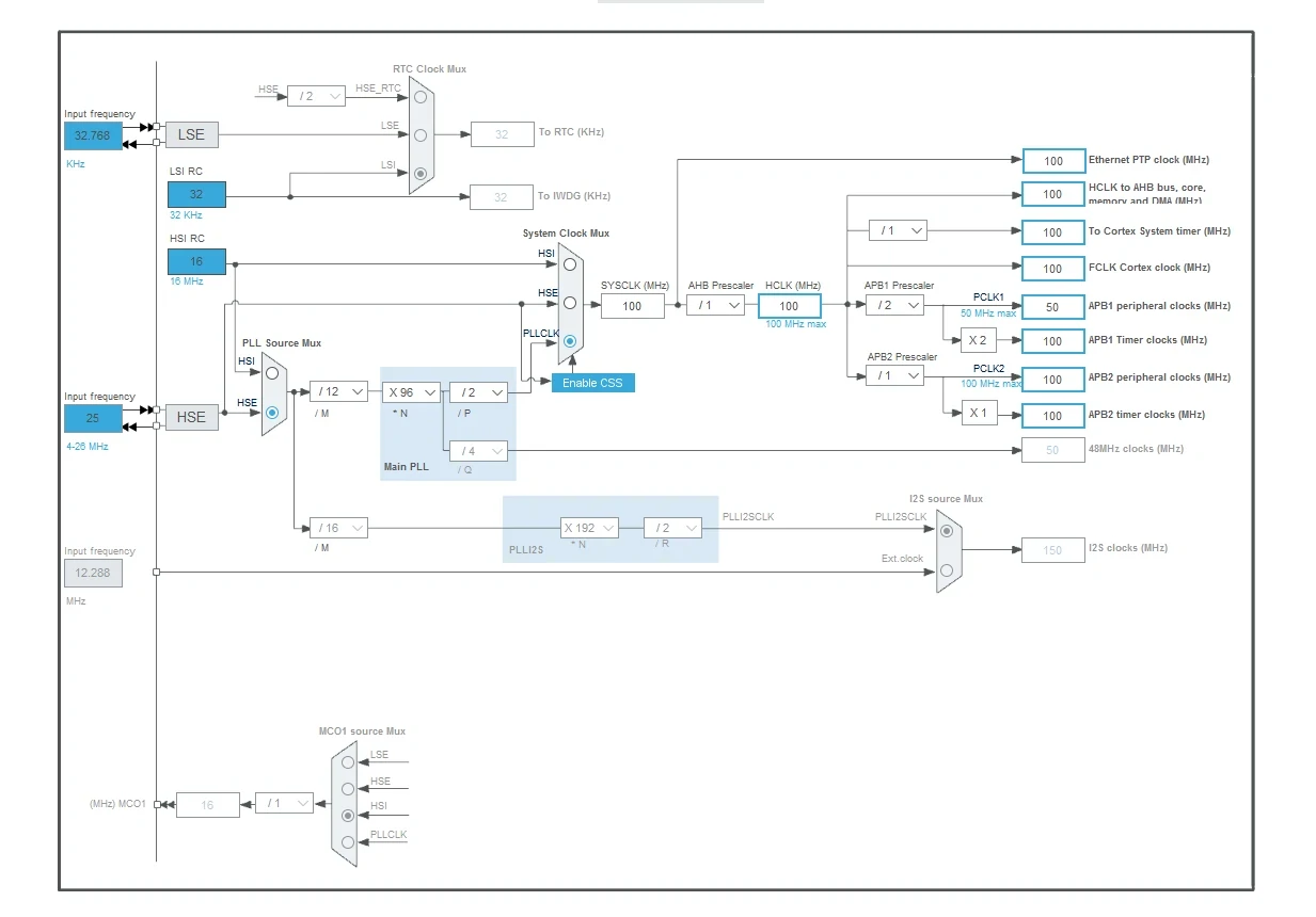
MCU程序使用STM32CUDEMX固件库进行编程:
接下来是编程:
时钟配置:
默认将IO引脚输出设置为高电平:
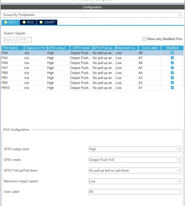
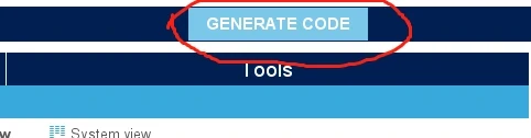
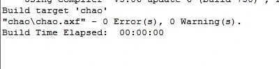
点击生成代码:
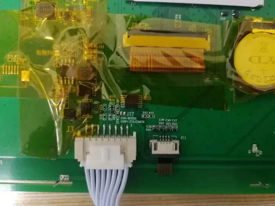
硬件连接:
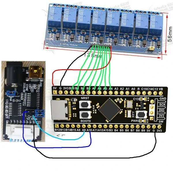
根据电路图连接:
STONE屏幕后方的J17跳线断开连接,选择TLL电平,并与MCU通信:
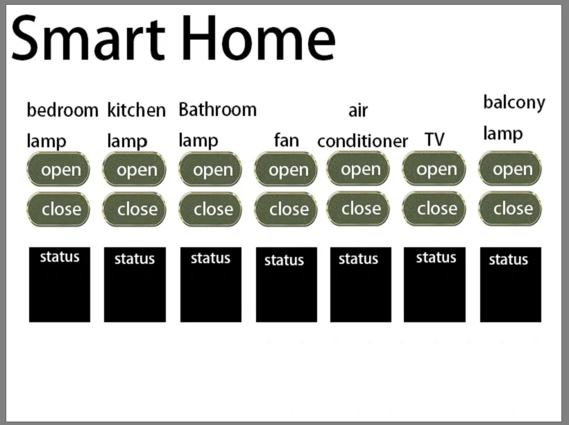
使用Photoshop设计页面上显示的底图:
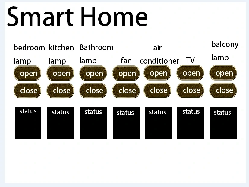
渲染效果已准备就绪:
GUI TOOL
依次添加触控按钮:
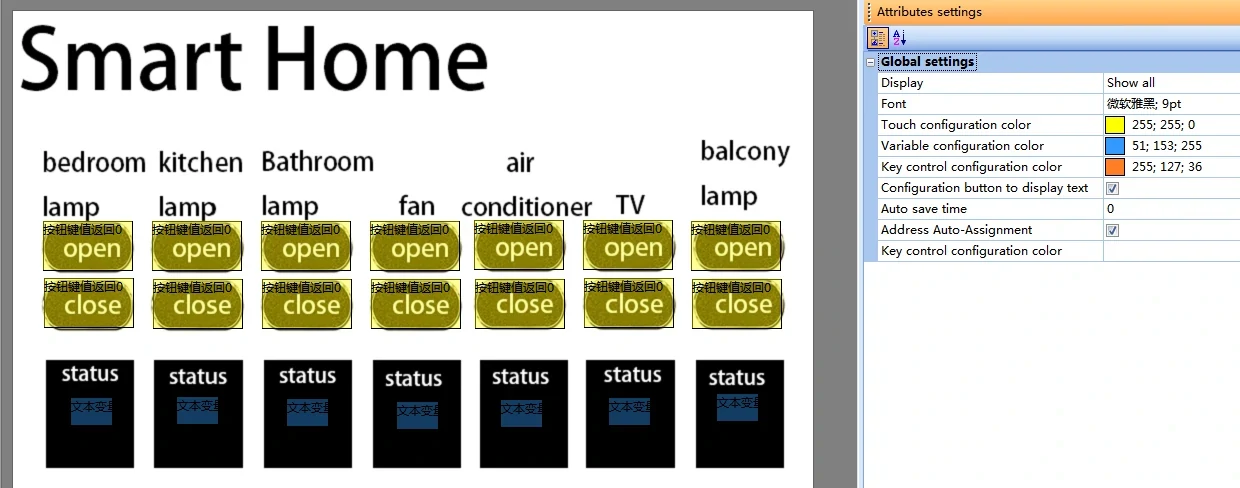
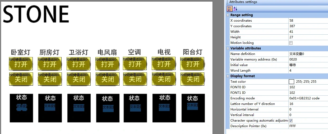
变量地址分配:
Bedroom light on:0x0001
Kitchen light on: 0x0002
Switch on the bathroom lamp: 0x0003
Electric fan on: 0x0004
Air conditioning on: 0x0005
TV on: 0x0006
Balcony light on: 0x0007
Bedroom lights off: 0x0011
Kitchen light off: 0x0012
Switch off the bathroom lamp: 0x0013
Electric fan off: 0x0014
Air conditioning off: 0x0015
TV off: 0x0016
Balcony light off: 0x0007
状态显示文本地址:
然后添加文本显示控制:
Bedroom light: 0x0020
Kitchen light: 0x0030
Bathroom lamp: 0x0040
Electric fan: 0x0050
Air conditioning: 0 x0060
TV: 0 x0070
Balcony light: 0x0080
设置完成后,不要点击编译按钮以生成需要导入到屏幕的文件
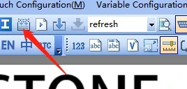
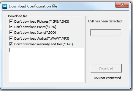
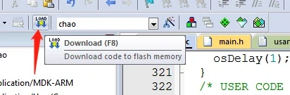
将屏幕的USB插入并点击“下载”以等待下载成功:
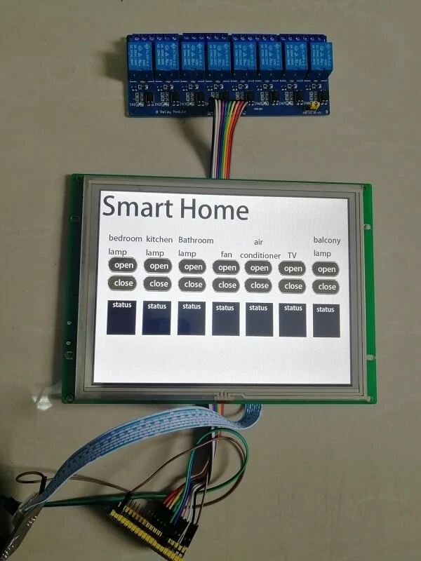
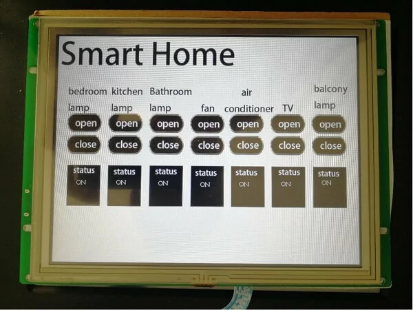
屏幕显示效果如下:
源代码分析
MCU使用串口1与触摸屏进行通信,波特率设置为115200
void MX_USART1_UART_Init(void)
{
huart1.Instance = USART1;
huart1.Init.BaudRate = 115200;//
huart1.Init.WordLength = UART_WORDLENGTH_8B;
huart1.Init.StopBits = UART_STOPBITS_1;
huart1.Init.Parity = UART_PARITY_NONE;
huart1.Init.Mode = UART_MODE_TX_RX;
huart1.Init.HwFlowCtl = UART_HWCONTROL_NONE;
huart1.Init.OverSampling = UART_OVERSAMPLING_16;
if (HAL_UART_Init(&huart1) != HAL_OK)
{
Error_Handler();
}
}
The configuration of HAL library GPIO is as follows:
void MX_GPIO_Init(void)
{
GPIO_InitTypeDef GPIO_InitStruct = {0};
/* GPIO Ports Clock Enable */
__HAL_RCC_GPIOC_CLK_ENABLE();
__HAL_RCC_GPIOH_CLK_ENABLE();
__HAL_RCC_GPIOA_CLK_ENABLE();
__HAL_RCC_GPIOB_CLK_ENABLE();
/*Configure GPIO pin Output Level */
HAL_GPIO_WritePin(GPIOA, A8_Pin|A7_Pin|A6_Pin|A5_Pin, GPIO_PIN_SET);
/*Configure GPIO pin Output Level */
HAL_GPIO_WritePin(GPIOB, A4_Pin|A3_Pin|A2_Pin|A1_Pin, GPIO_PIN_SET);
/*Configure GPIO pins : PAPin PAPin PAPin PAPin */
GPIO_InitStruct.Pin = A8_Pin|A7_Pin|A6_Pin|A5_Pin;
GPIO_InitStruct.Mode = GPIO_MODE_OUTPUT_PP;
GPIO_InitStruct.Pull = GPIO_NOPULL;
GPIO_InitStruct.Speed = GPIO_SPEED_FREQ_LOW;
HAL_GPIO_Init(GPIOA, &GPIO_InitStruct);
/*Configure GPIO pins : PBPin PBPin PBPin PBPin */
GPIO_InitStruct.Pin = A4_Pin|A3_Pin|A2_Pin|A1_Pin;
GPIO_InitStruct.Mode = GPIO_MODE_OUTPUT_PP;
GPIO_InitStruct.Pull = GPIO_NOPULL;
GPIO_InitStruct.Speed = GPIO_SPEED_FREQ_LOW;
HAL_GPIO_Init(GPIOB, &GPIO_InitStruct);
}
发送寄存器的发送格式根据手册设置,并使用GB2312中文字符编码库:
例如:
The "off" code is B9D8 and the "closed" code is B1D5
The inside code of "open" is B4F2, and the inside code of "open" is BFAA
Refresh all display states before MCU initialization:
data_send[4]=0x00;//
data_send[5]=0x20;//
data_send[6]=0xB9;//
data_send[7]=0xD8;
data_send[8]=0xB1;
data_send[9]=0xD5;
UART1_Send_Array(data_send,12);//
data_send[5]=0x30;//
UART1_Send_Array(data_send,12);//
data_send[5]=0x40;//
UART1_Send_Array(data_send,12);//
data_send[5]=0x50;//
UART1_Send_Array(data_send,12);//
data_send[5]=0x60;//
UART1_Send_Array(data_send,12);//
data_send[5]=0x70;//
UART1_Send_Array(data_send,12);//
data_send[5]=0x80;//
UART1_Send_Array(data_send,12);//
Receive the data sent by the screen to the MCU, and control the status of IO:
if ((char *)buffer != NULL)
{
if (strlen((char *)buffer) == 0)
{
//buffer
}
else//
{
switch(buffer[5])
{
case 0x01 : HAL_GPIO_WritePin(A1_GPIO_Port,A1_Pin,GPIO_PIN_RESET); break;//
case 0x02 : HAL_GPIO_WritePin(A2_GPIO_Port,A2_Pin,GPIO_PIN_RESET); break;//
case 0x03 : HAL_GPIO_WritePin(A3_GPIO_Port,A3_Pin,GPIO_PIN_RESET); break;//
case 0x04 : HAL_GPIO_WritePin(A4_GPIO_Port,A4_Pin,GPIO_PIN_RESET); break;//
case 0x05 : HAL_GPIO_WritePin(A5_GPIO_Port,A5_Pin,GPIO_PIN_RESET); break;//
case 0x06 : HAL_GPIO_WritePin(A6_GPIO_Port,A6_Pin,GPIO_PIN_RESET); break;//
case 0x07 : HAL_GPIO_WritePin(A7_GPIO_Port,A7_Pin,GPIO_PIN_RESET); break;//
case 0x11 : HAL_GPIO_WritePin(A1_GPIO_Port,A1_Pin,GPIO_PIN_SET); break;//
case 0x12 : HAL_GPIO_WritePin(A2_GPIO_Port,A2_Pin,GPIO_PIN_SET); break;//
case 0x13 : HAL_GPIO_WritePin(A3_GPIO_Port,A3_Pin,GPIO_PIN_SET); break;//
case 0x14 : HAL_GPIO_WritePin(A4_GPIO_Port,A4_Pin,GPIO_PIN_SET); break;//
case 0x15 : HAL_GPIO_WritePin(A5_GPIO_Port,A5_Pin,GPIO_PIN_SET); break;//
case 0x16 : HAL_GPIO_WritePin(A6_GPIO_Port,A6_Pin,GPIO_PIN_SET); break;//
case 0x17 : HAL_GPIO_WritePin(A7_GPIO_Port,A7_Pin,GPIO_PIN_SET); break;//
}
}
CLR();//
}
Determine the IO's status, and display the current output status feedback screen
// Determine the value of IO and display the corresponding status value in the status box if(!HAL_GPIO_ReadPin(A1_GPIO_Port,A1_Pin))//
{//
data_send[4]=0x00;//
data_send[5]=0x20;//
data_send[6]=0xB4;//
data_send[7]=0xF2;
data_send[8]=0xBF;
data_send[9]=0xAA;
UART1_Send_Array(data_send,12);//
}
else
{//
data_send[4]=0x00;//
data_send[5]=0x20;//
data_send[6]=0xB9;//
data_send[7]=0xD8;
data_send[8]=0xB1;
data_send[9]=0xD5;
UART1_Send_Array(data_send,12);//
}
发送寄存器的发送格式根据手册设置,并使用GB2312中文字符编码库:
例如:
接收屏幕发送至MCU的数据,并控制IO状态:
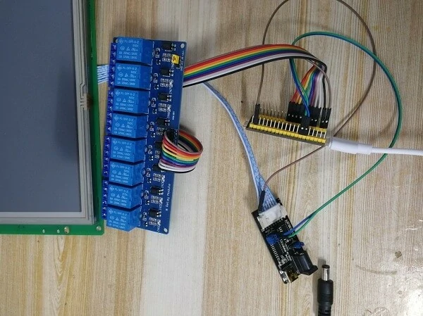
STONE串口屏 + STM32 MCU + 继电器模块控制智能家居设备效果示意图