STM32 串口屏+ STONE 串口屏介绍
STONE 的串口驱动STONE串口屏,可通过MCU的串口进行通信,且该STONE串口屏的 UI 逻辑设计可直接使用 STONE官网提供的STONE设计师软件进行设计,这对于我们来说非常方便。因此,我计划使用它来制作一个简单的家电控制器,包括对各种灯光(客厅、厨房、儿童房、卫生间)的控制。同时,可采集室内外温度、湿度及空气质量数据。此为简单演示,可通过我提供的代码进行二次开发。关于STONE屏幕的基本教程可访问官网:官网提供型号、用户手册、设计文档及视频教程等丰富资料。
UI界面设计
我使用Photoshop设计了以下两个UI页面:
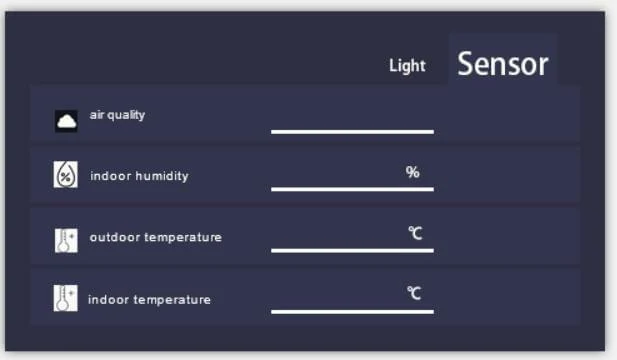
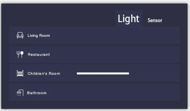
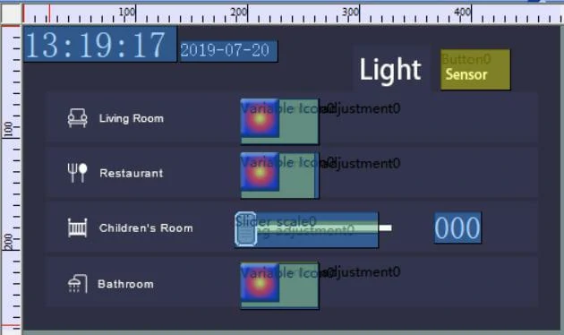
该项目共包含上述两个页面。右上角的“灯光”和“传感器”是这两个页面的切换按钮。
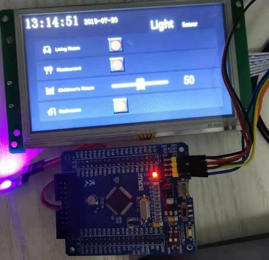
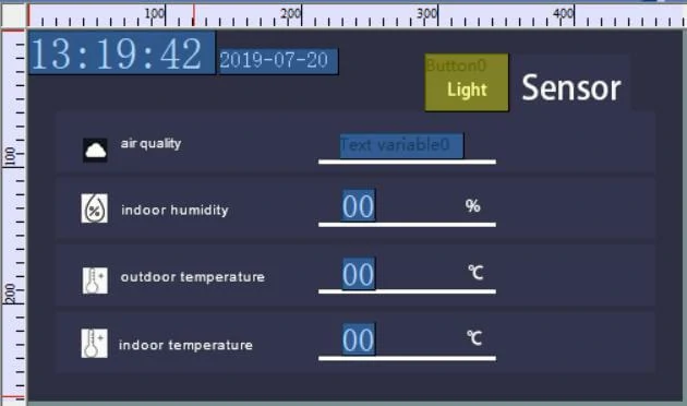
在“灯光”页面,您可以控制家中各种灯光。在“传感器”页面,您可以查看各种传感器检测到的数值。
在设计上述两页后,可通过STONE官网提供的STONE Designer软件进行按钮逻辑设计。
需特别注意,此处用于时间显示的时钟源为STONE串口屏的时钟源,而非MCU时钟源。
TAB页面切换效果
在STONE Designer中未找到TAB页面切换组件,因此我采用了另一种方法实现TAB页面切换效果。
通过观察提供的两张UI图片可以发现,上述两张图片分别是“Light”和“Sensor”文字,其区别在于像素大小不同,因此只需将两张图片中像素位置相同的文字设置为相同,然后通过时间和日期左上角作为参考,即可实现TAB切换效果。
按钮逻辑
以“客厅”按钮为例。当用户按下此按钮时,STONE串口STONE串口屏将通过串口发送相应的协议指令。收到此指令后,用户的MCU将解析协议以控制与MCU连接的灯光的切换状态。
传感器采集
以“空气质量”为例: 若要获取室内空气质量,需通过MCU采集空气质量传感器数据。MCU通过算法比较空气质量优劣后,将结果通过串口发送至存储区域,显示为“良好”或“不良”,并更新“Text variable0”的显示内容,用户即可直观查看空气质量状况。
这些内容将在MCU代码中详细说明。
STM32 串口屏MCU通信
STM32是大家熟悉的MCU,是国际上常见的MCU型号。因此,本项目中使用的 STM32 MCU 具体型号为 STM32F103RCT6。STM32 系列产品丰富,可满足市场多样化需求。其内核可分为 Cortex-M0、M3、M4 和 M7,每个内核又可细分为主流、高性能和低功耗版本。从学习角度出发,可选择F1和F4系列。F1代表基础型号,基于Cortex-M3内核,主频为72MHz;F4代表高性能型号,基于Cortex-M4内核,主频为180MHz。对于F1、F4(429系列及以上),除了核心架构和主频的提升外,升级的明显特征是增加了串口屏控制器和摄像头接口,支持SDRAM,这些差异在项目选型时应优先考虑。然而,从大学教学和用户初学者的角度来看,F1系列仍是首选。目前,F1系列的STM32在市场上拥有最多的材料和产品。关于STM32 SCM开发环境的安装和程序下载方法,在此不再赘述。
GPIO初始化
在本项目中,我们共使用了4个GPIO,其中一个为PWM输出引脚。
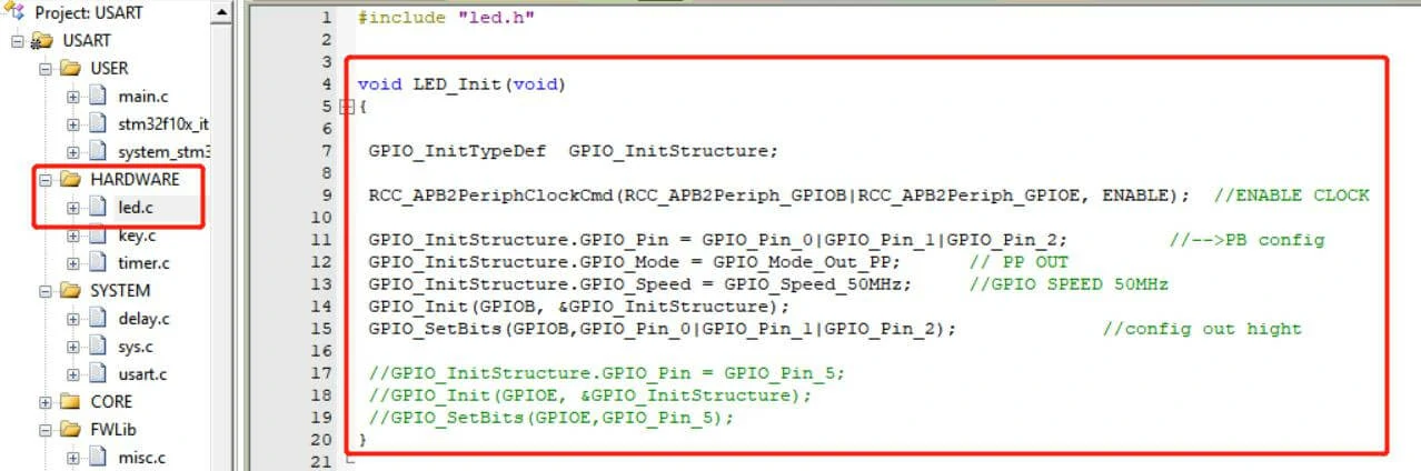
这是一个通过变量名称即可直观理解的函数。
串口初始化
串口初始化部分位于uart.c文件中:
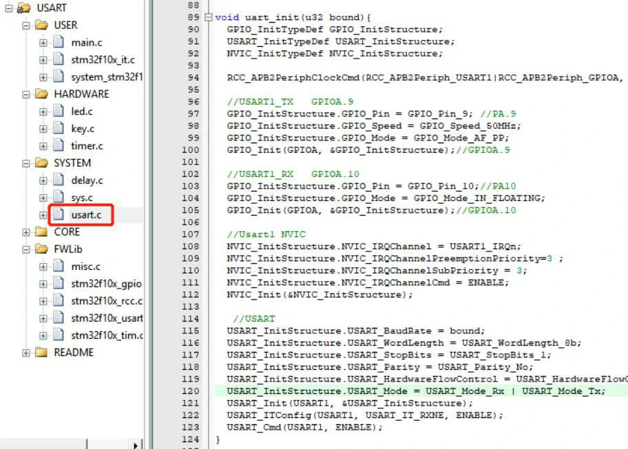
然后在主函数中调用uart_init函数,将串口波特率设置为115200。引脚使用PA9/PA10
PWM初始化
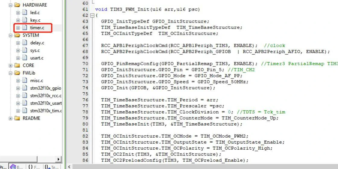
具体步骤
- 设置RCC时钟;2. 设置GPIO时钟;GPIO模式应设置为GPIO_Model_AF_PP,或在需要引脚映射时调用GPIO_PinRemapConfig()函数。3. 设置TIMx定时器的相关寄存器;4. 设置TIMx定时器的PWM相关寄存器; A. 设置PWM模式。设置占空比(公式计算)C. 设置输出比较极性(之前已介绍)D. 最重要的是,启用 TIMx 的输出状态并启用 TIMx 的 PWM 输出;完成相关设置后,通过 TIMx_Cmd() 函数启用 TIMx 定时器以获得 PWM 输出。在主函数中调用此 TIM3_PWM_Init 函数。
逻辑代码编写
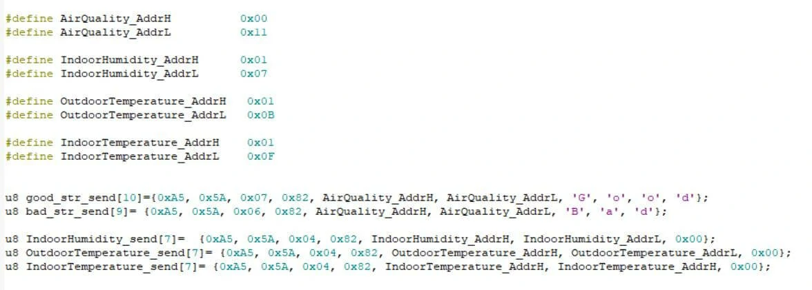
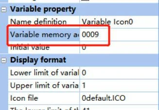
显示组件地址定义
显示组件具有独立地址,此处将其全部定义为宏:
串行数据接收
查看STONE串口屏的信息,可以发现按下按钮时,STONE串口屏的串口会发送格式正确的协议,用户MCU可接收并解析。按下按钮时,STONE串口屏的串口会发送包含用户数据的九个字节数据。串行数据接收在 Handler 中实现:
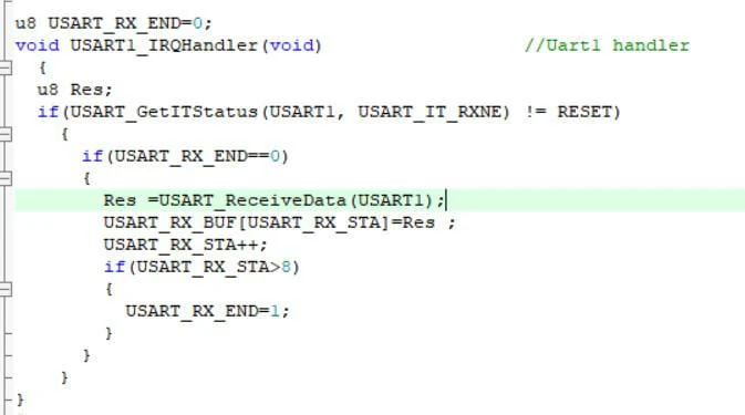
接收的数据存储在 “USART_RX_BUF” 数组中。在本项目中,接收长度是固定的。当接收长度超过9字节时,判断接收结束。
控制灯的开关状态
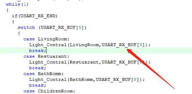
在主函数中,我编写了一些逻辑代码来控制灯的开关状态:
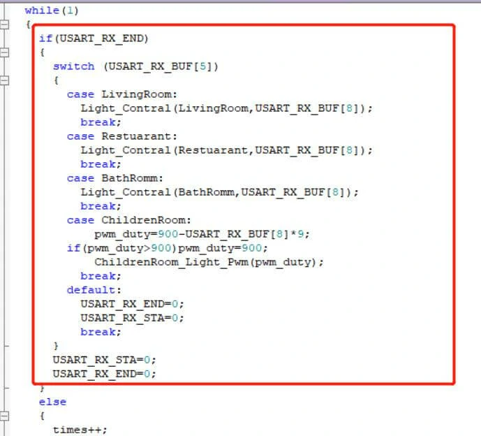
如我们所见,代码首先判断串口数据是否接收,当串口数据接收后,判断用户在STONE串口屏上按下了哪个按钮。STONE串口屏上的不同按钮具有不同的地址,可在 STONE Designer 软件中查看:
当用户按下“客厅”按钮时,STONE串口屏串口发送的数据的第四位和第五位是按钮的地址。由于这里所有按钮的第四位都设置为 0x00,因此可通过直接判断第五位数据来确定用户按下了哪个按钮。获取用户按下的按钮后,需判断按钮按下时接收的用户数据,即STONE串口屏发送数据的第八位。因此,我们进行如下控制:
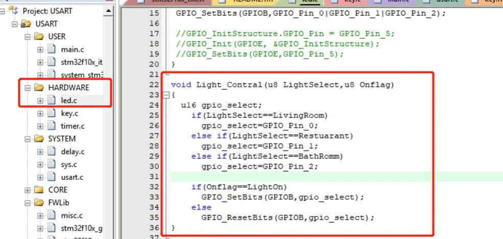
将按钮地址参数和用户数据写入“Light_Contral”函数以控制灯光的开关状态。Light_Contral函数实体如下:
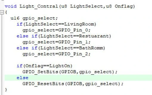
如你所见,如果按钮地址为“客厅”且用户数据为“LightOn”,则MCU的PB0引脚设置为高电平输出,灯光亮起。其他三个按钮类似,此处不再赘述。
PWM输出
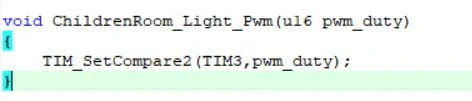
在我设计的UI中,有一个滑动调节器,用于控制“儿童房”灯光的亮度。MCU通过PWM实现。PWM输出引脚为PB5。代码如下:
滑动调节器设置为最小值0x00和最大值0x64。滑动时,STONE串口屏的串口会发送相关地址和数据,然后通过调用以下函数设置PWM输出的占空比:
传感器采集
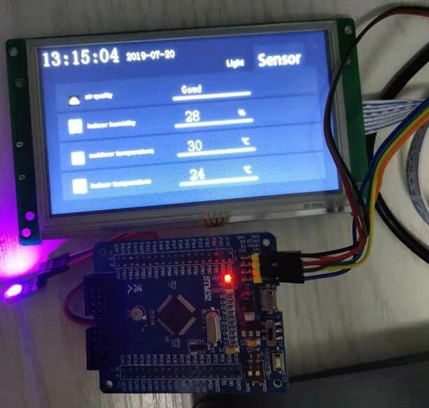
在STONE串口屏的“传感器”页面上有四个传感器数据。
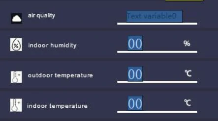
这些数据在STONE串口屏中也有存储地址,我们可以通过MCU的串口向这些地址写入数据来更改其实际内容。这里我做了一个简单的代码实现:
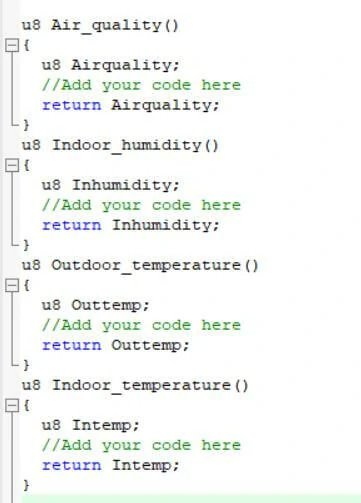
显示数据每5秒更新一次,我只写了一个简单的传感器采集函数演示,因为我手头没有这些传感器。
在实际项目开发中,这些传感器可能是通过ADC采集的数据,或是通过IIC、UART、SPI等通信接口采集的数据。您只需将这些数据作为返回值写入对应的函数即可。
实际运行效果(STM32触摸测试STONE 7英寸TFTSTONE串口屏)