- Arduino Uno项目介绍
由于个人兴趣,我接触了Arduino UNO和STONE LCD模块项目的开发已有两周时间,发现Arduino非常简单、方便且实用。因此我想用Arduino做一个简单的演示。我家中有一块 MFRC522 模块,曾在大学时使用过,但当时是通过 STM32 与 MFRC522 模块进行通信,因此需要自行编写 MFRC522 模块的驱动程序,这相当复杂。
Arduino自带MFRC522库文件,因此无需自行编写驱动程序,这将大大简化使用流程。
Arduino Uno连接STONE LCD
我需要制作一个演示项目,能够读取MI卡数据并将其显示在STONE串口屏上。
根据上述需求,所需材料如下:
- Arduino开发板
- MFRC522模块
- 串口屏
- MI卡
STONE 串口屏连接Arduino UNO项目硬件
该项目中包含3个电子模块,我将逐一介绍。
串口屏( STONE STVC050WT-01)
在本项目中,我计划使用STONE STVC050WT-01显示屏模块来显示MFRC522读取的卡数据。
驱动芯片已集成在显示屏内部,并提供可供用户使用的开发软件。用户只需通过电脑在设计好的UI图片中添加按钮和文本框,然后生成配置文件并下载到显示模块中。
STVC050WT-01通过UART-TTL信号与MCU进行通信。
STONE LCD开发步骤
STONE显示屏开发的三步流程:
- 使用STONE TOOL软件设计显示逻辑和按钮逻辑,并将设计文件下载到显示模块。
- MCU通过串口与STONE 串口屏进行通信。
- 基于步骤2获取的数据,MCU执行其他操作。
STONE TOOLBox(图形用户界面设计软件)
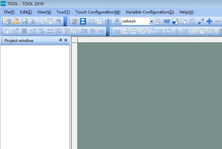
- 从官网下载最新版本的STONE TOOL软件(当前版本为TOOL2019),并安装。
- 安装完成后,将打开以下界面:
- 点击左上角的“文件”按钮创建新项目,具体操作将在后续章节中详细说明。
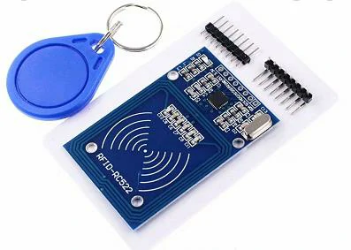
MFRC522是NXP推出的低电压、低成本、小型非接触式读写卡芯片,是智能电表及便携式手持设备开发的理想选择。
采用先进的调制和解调技术,MFRC522在13.56MHz频率下完全集成了所有类型的被动式非接触通信模式和协议。支持ISO14443A的多层应用。内部发射器部分驱动读卡器天线与ISO14443A/MIFARE卡和应答器进行通信,无需额外电路。接收部分提供强大的解调和解码电路,用于处理符合ISO14443A标准的应答器信号。数字部分处理ISO14443A帧和错误检测(奇偶校验和CRC)。MFRC522支持MIFARE高速非接触式通信,双向数据传输速率可达424kbit/s。
MFRC522 模块特点
- 高集成度调制与解调电路;
- 支持 ISO/IEC 14443 Type A 和 MIFARE 通信协议;
- 在读卡器模式下,与 ISO 14443A/MIFARE 的通信距离可达 50mm,具体取决于天线长度。
- 支持ISO 14443的更高传输速率:212kbit/s和424kbit/s。
- SPI接口,传输速率达10Mbit/s。
- 64字节发送和接收FIFO缓冲区;
- 内置温度传感器,当芯片温度过高时自动停止射频发射;
- 采用独立多组电源供应,避免模块间干扰并提升工作稳定性。
- CRC和奇偶校验功能。
- 内部振荡器连接至27.12MHz晶体;
- 2.5-3.3V低电压及低功耗设计;
- 工作温度范围:-30℃至+85℃;
- 超小型尺寸:5mm×5mm×0.85mm。
MFRC522模块应用
MFRC522适用于基于ISO/IEC 14443A标准的各种应用,要求低成本、小型化、高性能及单电源非接触式通信。
- 公共交通终端
- 便携式手持设备
- 非接触式公共电话
- 门锁
Arduino UNO
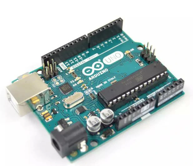
开发人员无需关注单片机编程的繁琐细节,提供易于使用的套件。Arduino UNO 还简化了微控制器的工作流程,但与其他系统相比,Arduino 在许多方面更具优势,特别适合教师、学生和业余爱好者:
- 便宜 — Arduino 开发板与其他平台相比价格非常低廉。最便宜的 Arduino UNO 版本可自行组装,即使购买成品也无需超过 $30。
- 简单编程环境——Arduino 编程环境易于初学者学习使用,同时能为高级用户提供足够的先进应用。
- 软件开源且可扩展——Arduino 软件开源,可由经验丰富的程序员扩展。Arduino 编程语言可通过 C++ 库进行扩展,
- 开源且可扩展的硬件——Arduino 开发板基于 Atmel 的 ATMEGA8 和 ATMEGA168/328 微控制器。Arduino 采用 Creative Commons 许可证,因此经验丰富的电路设计师可以设计自己的模块来扩展或改进功能。即使对于一些相对缺乏经验的用户,也可以制作测试板来理解 Arduino 的工作原理,从而节省时间和成本。
Arduino 基于 AVR 平台,对 AVR 库进行了两次编译和封装。端口已打包,寄存器、地址指针等无需额外处理。这大大降低了软件开发难度,适合非专业爱好者使用。
Arduino UNO开发环境
Arduino IDE对初学者非常友好,且具有高度灵活性。Arduino语言基于Wiring语言开发,是AVR-GCC库的二次封装。它不需要过多的SCM或编程基础,因此在简单学习后即可快速开发。
Arduino 开发环境是 Arduino IDE,可从互联网下载。
安装 Arduino IDE 后,打开软件将出现以下界面:
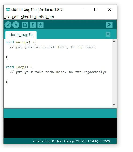
Arduino IDE 默认创建两个函数:setup 函数和 loop 函数。
互联网上有大量 Arduino 教程。若不理解,可自行查阅相关资料。
Arduino串口屏项目实现过程
硬件连接
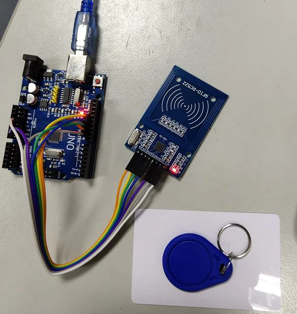
为了确保后续编写代码的顺利进行,我们必须首先验证硬件连接的可靠性。
本项目仅使用了三块硬件:
-
- Arduino UNO开发板
- STONE STVC050WT-01 TFT-LCD 显示屏
- MFRC522模块
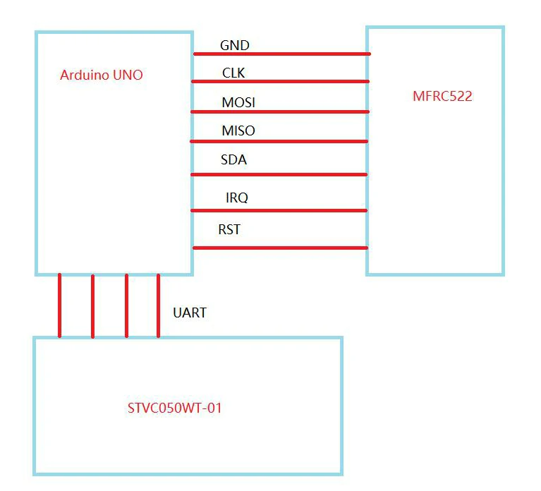
Arduino UNO开发板与STVC050WT-01TFT-串口屏通过UART接口连接,Arduino UNO开发板与MFRC522模块通过SPI接口连接。经过仔细规划,我们可以绘制出以下接线图:
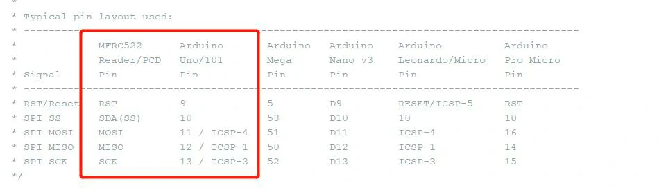
具体引脚连接如下:
确保硬件连接无误后,继续进行下一步操作。
TFT LCD用户界面设计
首先,我们需要设计一张图片,可使用PhotoShop或其他图像设计工具进行设计。设计完成后,将图片保存为JPG格式。
打开STONE TOOL软件并创建新项目:
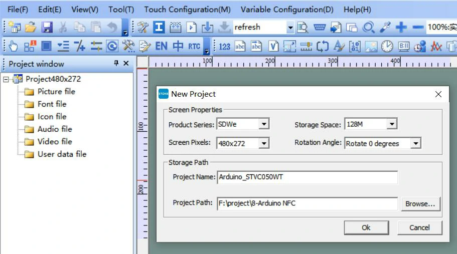
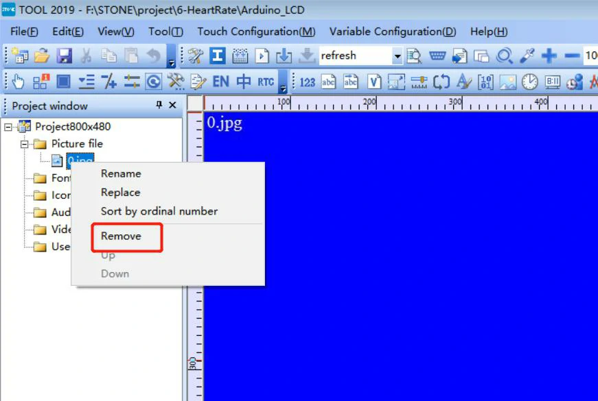
删除新项目中默认加载的图像,并添加我们设计的UI图像。
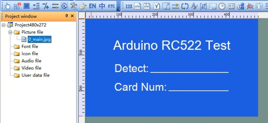
添加文本显示组件,设计显示数字和小数点,获取文本显示组件在显示屏中的存储位置。
效果如下:
STONE 人机交互界面生成配置文件
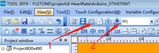
UI设计完成后,可生成配置文件并下载至STVC050WT-01显示屏,具体操作详见STONE开发资料。
首先执行步骤1,然后将USB闪存盘插入电脑,磁盘图标将显示出来。然后点击“下载到U盘”将配置文件下载到USB闪存盘,再将USB闪存盘插入STVC050WT-01完成升级。
MFRC522模块
无需对MFRC522模块进行编程。只需确保硬件连接可靠。
带完整代码的Arduino库文件
打开Arduino IDE并找到以下按钮:
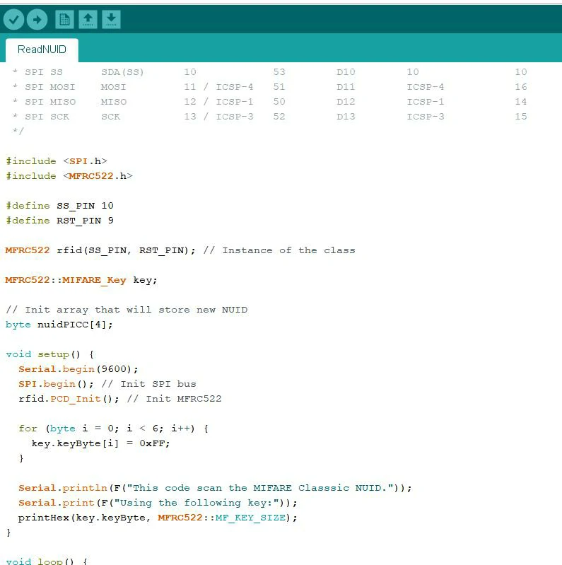
安装完成后,可在Arduino的LIB库文件夹中找到MFRC522的示例代码:
双击文件打开。
此示例可直接测试。编译并将代码下载到Arduino开发板后,若硬件连接无误,可在串口调试工具中看到MFRC522的数据。
Double-click the file to open it.
 This
This
MFRC522模块
无需对MFRC522模块进行编程。只需确保硬件连接可靠。
带完整代码的Arduino库文件
打开Arduino IDE并找到以下按钮:
* --------------------------------------------------------------------------------------------------------------------
* Example sketch/program showing how to read new NUID from a PICC to serial.
* --------------------------------------------------------------------------------------------------------------------
* This is an MFRC522 library example; for further details and other examples see: https://github.com/miguelbalboa/rfid
*
* Example sketch/program showing how to the read data from a PICC (that is: an RFID Tag or Card) using an MFRC522 based RFID
* Reader on the Arduino SPI interface.
*
* When the Arduino and the MFRC522 module are connected (see the pin layout below), load this sketch into Arduino IDE
* then verify/compile and upload it. To see the output: use Tools, Serial Monitor of the IDE (hit Ctrl+Shft+M). When
* you present a PICC (that is: an RFID Tag or Card) at reading distance of the MFRC522 Reader/PCD, the serial output
* will show the type, and the NUID if a new card has been detected. Note: you may see "Timeout in communication" messages
* When removing the PICC from reading distance too early.
*
* @license Released into the public domain.
*
*/
#include
#include
#define SS_PIN 10
#define RST_PIN 9
MFRC522 rfid(SS_PIN, RST_PIN); // Instance of the class
MFRC522::MIFARE_Key key;
// Init array that will store new NUID
byte nuidPICC[4];
void setup() {
Serial.begin(9600);
SPI.begin(); // Init SPI bus
rfid.PCD_Init(); // Init MFRC522
for (byte i = 0; i < 6; i++) {
key.keyByte[i] = 0xFF;
}
Serial.println(F("This code scan the MIFARE Classsic NUID."));
Serial.print(F("Using the following key:"));
printHex(key.keyByte, MFRC522::MF_KEY_SIZE);
}
void loop() {
// Reset the loop if no new card present on the sensor/reader. This saves the entire process when idle.
if ( ! rfid.PICC_IsNewCardPresent())
return;
// Verify if the NUID has been readed
if ( ! rfid.PICC_ReadCardSerial())
return;
Serial.print(F("PICC type: "));
MFRC522::PICC_Type piccType = rfid.PICC_GetType(rfid.uid.sak);
Serial.println(rfid.PICC_GetTypeName(piccType));
// Check is the PICC of Classic MIFARE type
if (piccType != MFRC522::PICC_TYPE_MIFARE_MINI &&
piccType != MFRC522::PICC_TYPE_MIFARE_1K &&
piccType != MFRC522::PICC_TYPE_MIFARE_4K) {
Serial.println(F("Your tag is not of type MIFARE Classic."));
return;
}
if (rfid.uid.uidByte[0] != nuidPICC[0] ||
rfid.uid.uidByte[1] != nuidPICC[1] ||
rfid.uid.uidByte[2] != nuidPICC[2] ||
rfid.uid.uidByte[3] != nuidPICC[3] ) {
Serial.println(F("A new card has been detected."));
// Store NUID into nuidPICC array
for (byte i = 0; i < 4; i++) {
nuidPICC[i] = rfid.uid.uidByte[i];
}
Serial.println(F("The NUID tag is:"));
Serial.print(F("In hex: "));
printHex(rfid.uid.uidByte, rfid.uid.size);
Serial.println();
Serial.print(F("In dec: "));
printDec(rfid.uid.uidByte, rfid.uid.size);
Serial.println();
}
else Serial.println(F("Card read previously."));
// Halt PICC
rfid.PICC_HaltA();
// Stop encryption on PCD
rfid.PCD_StopCrypto1();
}
/**
* Helper routine to dump a byte array as hex values to Serial.
*/
void printHex(byte *buffer, byte bufferSize) {
for (byte i = 0; i < bufferSize; i++) {
Serial.print(buffer[i] < 0x10 ? " 0" : " ");
Serial.print(buffer[i], HEX);
}
}
/**
* Helper routine to dump a byte array as dec values to Serial.
*/
void printDec(byte *buffer, byte bufferSize) {
for (byte i = 0; i < bufferSize; i++) {
Serial.print(buffer[i] < 0x10 ? " 0" : " ");
Serial.print(buffer[i], DEC);
}
}
双击文件打开。
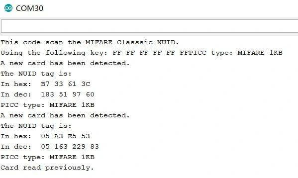
打开Arduino串口监听器,你可以看到以下输出:
这段代码非常简单,我相信你一眼就能看懂。我不得不说,Arduino的模块化编程非常方便,甚至不需要理解UART和SPI驱动程序的实现细节。
当然,上述代码是官方示例,我仍需进行一些修改以将数据显示到 STONE 的显示屏上。
通过Arduino UNO将数据显示到STONE显示屏
首先,我们需要获取STONE显示屏中显示MFRC522数据的组件地址:
在我的项目中,地址如下:
MFRC522检测结果输出地址:0x0001
MFRC522卡片结果输出地址:0x0004
如果您需要更改相应区域的显示内容,可以通过Arduino UNO的串口向显示屏的相应地址发送数据来修改显示内容。
修改后的代码如下:
/*
* --------------------------------------------------------------------------------------------------------------------
* Example sketch/program showing how to read new NUID from a PICC to serial.
* --------------------------------------------------------------------------------------------------------------------
* This is an MFRC522 library example; for further details and other examples see: https://github.com/miguelbalboa/rfid
*
* Example sketch/program showing how to read data from a PICC (that is: an RFID Tag or Card) using an MFRC522 based RFID
* Reader on the Arduino SPI interface.
*
* When the Arduino and the MFRC522 module are connected (see the pin layout below), load this sketch into Arduino IDE
* then verify/compile and upload it. To see the output: use Tools, Serial Monitor of the IDE (hit Ctrl+Shft+M). When
* you present a PICC (that is: an RFID Tag or Card) at reading distance of the MFRC522 Reader/PCD, the serial output
* will show the type, and the NUID if a new card has been detected. Note: you may see "Timeout in communication" messages
* When removing the PICC from reading distance too early.
*
* @license Released into the public domain.
*
*/
#include
#include
#define read_card_addr 0x01
#define read_num_addr 0x04
unsigned char read_card_status[8]= {0xA5, 0x5A, 0x05, 0x82,\
0x00, read_card_addr, 0x00, 0x00};
unsigned char read_card_num[10]= {0xA5, 0x5A, 0x07, 0x82, 0x00, \
read_num_addr, 0x00, 0x00,0x00,0x00};
#define SS_PIN 10
#define RST_PIN 9
MFRC522 rfid(SS_PIN, RST_PIN); // Instance of the class
MFRC522::MIFARE_Key key;
// Init array that will store new NUID
byte nuidPICC[4];
void setup() {
Serial.begin(115200);
SPI.begin(); // Init SPI bus
rfid.PCD_Init(); // Init MFRC522
for (byte i = 0; i < 6; i++) {
key.keyByte[i] = 0xFF;
}
// Serial.println(F("This code scan the MIFARE Classsic NUID."));
// Serial.print(F("Using the following key:"));
// printHex(key.keyByte, MFRC522::MF_KEY_SIZE);
}
void loop() {
// Reset the loop if no new card present on the sensor/reader. This saves the entire process when idle.
if ( ! rfid.PICC_IsNewCardPresent())
return;
// Verify if the NUID has been readed
if ( ! rfid.PICC_ReadCardSerial())
return;
// Serial.print(F("PICC type: "));
MFRC522::PICC_Type piccType = rfid.PICC_GetType(rfid.uid.sak);
// Serial.println(rfid.PICC_GetTypeName(piccType));
// Check is the PICC of Classic MIFARE type
if (piccType != MFRC522::PICC_TYPE_MIFARE_MINI &&
piccType != MFRC522::PICC_TYPE_MIFARE_1K &&
piccType != MFRC522::PICC_TYPE_MIFARE_4K) {
// Serial.println(F("Your tag is not of type MIFARE Classic."));
return;
}
if (rfid.uid.uidByte[0] != nuidPICC[0] ||
rfid.uid.uidByte[1] != nuidPICC[1] ||
rfid.uid.uidByte[2] != nuidPICC[2] ||
rfid.uid.uidByte[3] != nuidPICC[3] ) {
// Serial.println(F("A new card has been detected."));
read_card_status[7]=0x01;
Serial.write(read_card_status,8);
// Store NUID into nuidPICC array
for (byte i = 0; i < 4; i++) {
nuidPICC[i] = rfid.uid.uidByte[i];
}
read_card_num[6]=rfid.uid.uidByte[0];
read_card_num[7]=rfid.uid.uidByte[1];
read_card_num[8]=rfid.uid.uidByte[2];
read_card_num[9]=rfid.uid.uidByte[3];
Serial.write(read_card_num,10);
// Serial.println(F("The NUID tag is:"));
// Serial.print(F("In hex: "));
// printHex(rfid.uid.uidByte, rfid.uid.size);
// Serial.println();
//Serial.print(F("In dec: "));
//printDec(rfid.uid.uidByte, rfid.uid.size);
//Serial.println();
}
//else Serial.println(F("Card read previously."));
// Halt PICC
rfid.PICC_HaltA();
// Stop encryption on PCD
rfid.PCD_StopCrypto1();
}
/**
* Helper routine to dump a byte array as hex values to Serial.
*/
void printHex(byte *buffer, byte bufferSize) {
for (byte i = 0; i < bufferSize; i++) {
Serial.print(buffer[i] < 0x10 ? " 0" : " ");
Serial.print(buffer[i], HEX);
}
}
/**
* Helper routine to dump a byte array as dec values to Serial.
*/
void printDec(byte *buffer, byte bufferSize) {
for (byte i = 0; i < bufferSize; i++) {
Serial.print(buffer[i] < 0x10 ? " 0" : " ");
Serial.print(buffer[i], DEC);
}
}
MFRC522模块
无需对MFRC522模块进行编程。只需确保硬件连接可靠。
带完整代码的Arduino库文件
打开Arduino IDE并找到以下按钮:
