皮肤二号激光器可分解皮肤下的色素,去除色素沉着,多功能激光美容仪器可实现眉毛漂白、纹身去除、雀斑去除(雀斑、咖啡斑、老年斑、色素沉着)、眼线去除、太田痣等美容功能。本项目计划开发一款简单便携、成本低廉、性能稳定、操作简便的美容仪器。
该激光美容仪器采用5.6英寸STONE系列屏幕,配备背光,色彩丰富,通过串口与主控制板通信,触摸输入省去键盘,整体外观简洁大方。
主界面:
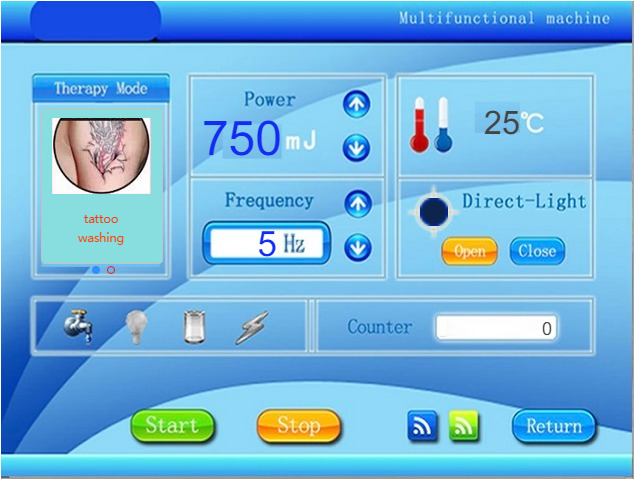
图(1)美容仪器界面
通过STONE DESIGNER(一款新型开发工具)设计的便捷滑块视图,可实现两种功能(眉毛清洁和纹身清洁)的切换。能量、频率的调节与选择可通过文本选择器部分实现,该部分与按钮控制、状态指示灯、温度显示、计数器等功能协调配合。界面呈现一致,直观且便捷。参见上文图(1)和图(2)。请查看附带视频以了解切换效果。
STONE 串口屏幕的特点
从使用旧版本的 STONE 串口屏幕到现在使用新版本的 STONE 串口屏幕,我感觉新版本的 STONE 屏幕更加方便且易于使用。新版本的 STONE 设计工具仍在功能升级过程中,新增了许多增强的视图控制功能,以丰富 STONE 屏幕界面的用户体验。然而,其中部分增强控件尚未开发完成,期待新版本能带来更多惊喜!上次我使用新版本的曲线功能进行监控项目时,曲线的实时绘制非常流畅,我认为新版本的屏幕应能同时绘制6通道的实时曲线,甚至更多通道,这表明主控速度已足够满足更高应用需求。
操作说明:
当切换至滑动模式进行纹身清洗时,串口反馈的命令为:
ST<0x11 0x20 0x00 0x0F slide_view1 0x00 0x00 0x00 0x00>ET
When switching to eyebrow washing through sliding mode, the serial port feedback instruction is as follows:
ST<0x11 0x20 0x00 0x0F slide_view1 0x00 0x00 0x00 0x01>ET
您还可以通过以下方式更改视图:
set_view: Toggles the interface by index number
ST < {” cmd_code “:” set_view “, “type” : “slide_view”, “widget” : “slide_view1”, “index” : 0} > ET switch to wash the tattoo
ST < {” cmd_code “:” set_view “, “type” : “slide_view”, “widget” : “slide_view1”, “index” : 1} > ET switch to wash the eyebrow
“set_auto_play” : automatic switch interface function
ST < {” cmd_code “:” set_auto_play “, “type” : “slide_view”, “widget” : “slide_view1”, “auto_play” : 0} > ET cancelled automatically
ST<{“cmd_code”:”set_auto_play”,”type”:”slide_view”,”widget”:”slide_view1″,”auto_play”:1000}>ET switch automatically at an interval of 1 second
ST < {” cmd_code “:” set_auto_play “, “type” : “slide_view”, “widget” : “slide_view1”, “auto_play” : 3000} > ET automatic switching between 3 seconds
Set the current view autoplay (automatically switch the interface)
get_view: reads the index number of the current interface. ST<{“cmd_code”:”get_view”,”type”:”slide_view”,”widget”:”slide_view1″}>ET
When the interface mode is in tattoo washing, the serial port feedback:
ST<0x11 0x20 0x00 0x0F slide_view1 0x00 0x00 0x00 0x00>ET
When the interface mode is in eyebrow washing, the serial port feedback:
ST<0x11 0x20 0x00 0x0F slide_view1 0x00 0x00 0x00 0x01>ET
滑块指示器1:
这是界面位置指示器。您可以在属性窗口中设置更醒目的颜色,使界面美观清晰。如图(4)所示,您可以设置指示器的带宽、高度、选定颜色、指示器大小以及指示器的X/Y位置(锚点X、锚点Y)。
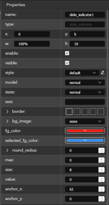
图(4)由位置指示的属性
png m2.jpg m2.jpg 屏幕显示会混乱!文本选择器用于调整一个值功率和频率调整都是此文本选择器控件的一部分。
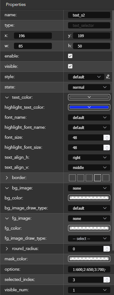
图(5)文本选择器属性
通过设置图(5)中的属性,文本选择器部分可与背景融合,其中背景色(bg color)、前景色(fg color)和遮罩色(mask color)均设置为透明色,且可见数(visible num)设为1。该效果可与图(1)结合查看。
这里的关键是选项。不连续的值应格式化如下:
1:6 00; 然后 50; 然后 00; 然后 50; “00; 收集 50; 对于 00; 50 的操作;
如果写成 100-900 且选中索引 = 600,将引发异常!
文本选择器部分指令:
0x1081 文本选择器值传递(整数类型,主动传递:选择器调整后立即传递)
数据格式:
value 表示数据段的最后四个字节
示例:(频率选择器控制名称 = text_s2,选项:5-50,当前值 16,再次选择 20)
串行助手接收的十六进制数据为:
53 54 3C 10 81 00 08 74 65 78 74 5F 73 32 00 00 00 14 3E 45 54 ???? OK
屏幕发送的命令为:
ST<0x10 0x81 0x00 0x08 text_s2 0x00 0x00 0x14 >ET text_s2 当前值:20 = 0x14
按钮功能按钮:
0x1001 按钮 键值自动传递
键值(数据段的最后一个字节):
0x01 按下 按钮被按下
0x02 释放按钮(按钮完成触发点击事件)
例如:
界面上的启动按钮(名称 = bt11):
ST<0x10 0x01 0x00 0x04 bt1 0x01>ET
串口助手返回十六进制数据:验证成功
53 54 3C 10 01 00 04 62 74 31 01 3E 45 54 ????. 53 54 3C 10 01 00 04 62 74 31 01 3E 45 54 ????
释放按钮(完成按钮点击操作),主动发出指令——以便对 62 74 31 02 进行解码!
ST<0x10 0x01 0x00 0x04 bt1 0x02>ET
串口助手返回十六进制数据:验证通过
53 54 3C 10 01 00 04 62 74 31 02 3E 45 54 ????. 53 54 3C 10 01 00 04 62 74 31 02 3E 45 54 ????
注意:按钮 bt1(ASCII 码 0x62 0x74 0x31)。
标签计数显示:
set_text 设置标签显示的文本
示例设置文本:
ST < {“ cmd_code ”:“ set_text ”, “type” : “label”, “widget” : “lable6”, ‘text’, “” 29} > ET verified OK
编程控制名称:
参见图(1)界面:
启动按钮名称 = bt1
停止按钮名称 = bt2
返回按钮名称 = bt3
打开按钮名称 = bt5
关闭按钮名称 = bt4
能量选择器名称 = text_s2 范围 600-950,间隔 50
频率选择器名称 = text_s1 范围 5-50,步长 1
温度区域标签名称 = label5
计数区域标签名称 = label6
激光指针图标名称 = image3
界面下载
点击主菜单下的“调试”和“下载”,选择美容仪器文件夹,系统将生成一个与项目同名的子文件夹;将STONE串口屏幕后方的拨动开关切换至“设备”位置。使用USB通信电缆将电脑直接连接至显示屏的USB接口。电脑上将弹出一个新磁盘文件夹。将项目同名子文件夹中的/default文件夹复制到显示器存储目录下的“default”文件夹。在弹出窗口中选择覆盖同名文件。复制完成后,关闭文件夹,弹出磁盘,拔掉USB下载线,重启显示器。
硬件连接与操作说明
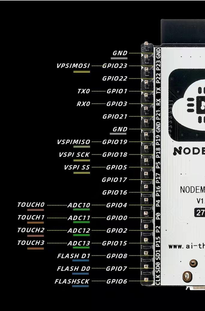
图(6)NODEMCU-32 串口位置
如图(6)所示,NodeMCU-32S 开发板的 TX0、RX0 和 GND 需连接至 STONE 串口接口板,如图(7)所示,以完成 HMI 信息交换。STONE串口接口上的232信号通过V1.2切换板转换为MCU接口所需的TX和RX信号,以实现电平匹配。在图(7)中,左侧为NodeMCU-32S开发板。蓝色(TX0)和红色(RX0)导线连接至V1.2适配器板的跳线位置(移除蓝色跳线适配器旁),黑色导线连接至GND。
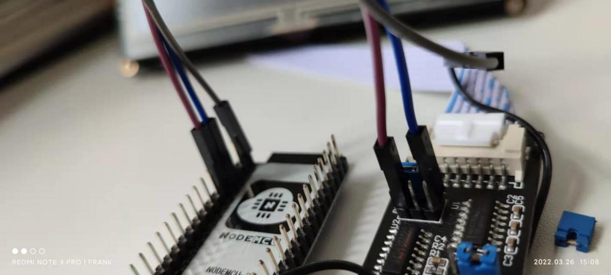
图(7)NODEMCU-32与STONE适配器板的连接
通信注意事项:适配器板必须同时连接至12V和USB。否则,通信将异常。
调试代码:
以下代码已编译并下载至NodeMCU-32S V1.3开发板。按图(7)所示连接。请参考附带视频查看测试效果。该代码采用三层嵌套结构实现简单启动、停止、开、关按钮解码,可实现更复杂的嵌套解码,并支持当前滑动视图滑动窗口组件的读取。ESP32通过按键点击和命令控制显示与输出。请查看视频效果。
/*
Frank 2022.08.15 多功能激光美容仪器
使用NodeMCU-32s在Arduino 1.8.13中使用ESP32
使用深圳的STONE HMI
*/
int LED_blue = 2; // IO2,打开LED(高电平为LED亮)
int ii = 0;
int iii = 0;
int f1 = 0;
int f2 = 0;
int f_Auto_mode = 1; //
int f_Hz = 1; // 1 = 20Hz, 2 = 50Hz
int DirectLight = 0; // 0 = 关闭 1 = 打开
int outPower = 0; // 0 = 关闭 1 = 打开
//——时间使用———-2022.08.15——
unsigned int led1s=0;
unsigned int time_1s=0;
unsigned int time_1m=0;
unsigned int time_1h=0;
void setup() {
Serial.begin(115200);
pinMode(LED_blue, OUTPUT);
}
void loop() {
int inChar;
// 读取串口发送的消息并简要解码:
if (Serial.available() > 0) {inChar = Serial.read();}
if (inChar == 0x62) { // 0x62 0x74 0x31 是“bt1”的开始键!
if (Serial.available() > 0){inChar = Serial.read();}
if (inChar == 0x74) {
f2 = 0;
如果 (Serial.available() > 0) { inChar = Serial.read();}
如果 (inChar == 0x31) { f1 = 1; outPower = 1; } // 开始
否则如果 (inChar == 0x32) { f1 = 2; outPower = 0; } // 停止
否则如果 (inChar == 0x35){ f1 = 3; DirectLight = 1;} // 打开
else if (inChar == 0x34){ f1 = 4; DirectLight = 0;} // 关闭
}
}
//—————-Direct Light 图片开关—————-
if(DirectLight == 1)
{
Serial.println(F(“ST<{\”cmd_code\“:\”set_visible\“,\”type\“:\”widget\“,\”widget\“:\”image3\“,\”visible\“:true}>ET”)); //
}else{
Serial.println(F(“ST<{\”cmd_code\“:\”set_visible\“,\”type\“:\”widget\“,\”widget\“:\”image3\“,\”visible\“:false}>ET”)); //
}
//——————输出功率——————————–
if(输出功率 == 1)
{
digitalWrite(LED_blue, HIGH); // 打开LED(HIGH表示高电平)
}else{
digitalWrite(LED_blue, LOW); // 打开LED(高电平为HIGH)
}
//————————————-结束———————
//—时间递增 ——
ii = ii + 1;
if(ii > 29){
if(f1 == 1){time_1s = time_1s + 1;}
else if(f2 == 1){time_1s = time_1s + 1;}
ii = 0;
}
if(time_1s >= 60){
time_1s = 0;
time_1m = time_1m + 1;
if(time_1m >= 60){
time_1m = 0;
time_1h = time_1h + 1;
}
}
}